Posts under this category displays latest news, useful articles, terms definitions, scientific explanations and more topics related to the water treatment industry.
What is Conductivity Definition
Water conductivity is a measurement of dissolved ions. Water conductivity indirectly measures ions by measuring the passage of electrons through a sample of water. Solutions which have a lot of dissolved ions will have a high conductivity. Solutions which have a low concentration of dissolved ions will have a low conductivity.
Water Conductivity: Pure Water vs Seawater
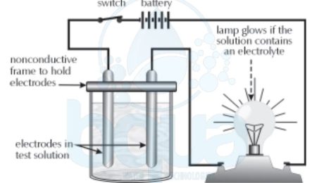
Conductance in a solution actually involves the movement of ions. Picture shows an apparatus which can be used to show that solutions of dissolved ions (dissolved salts) in water will pass the electric potential of a battery through them and allow the light bulb to light. Electrolyte definition is simply a solution which will conduct a current.
Water Conductivity Measurement Using Apparatus
Positively-charged ions are called “cationsâ€, negatively-charged ions are called “anions.†Cations are formed when one or more electrons are lost from an atom or a group of atoms, anions are formed when one or more electrons are gained by an atom or group of atoms. An electrolyte contains cations and anions. The more cations & anions present, the higher the conductivity. If the amount of current passing through a solution is measured with a conductivity meter, we can tell relatively how many ions are dissolved in the solution. When more current passes through the solution, we know more ions are present.
Water Conductivity decreases as temperature decreases, whereas the conductance of a solid conductor (such as a copper wire) increases with decreasing temperature. Water Conductance in would therefore appear to be different than in a solid, and it is. Water Conductivity actually occurs as a result of positive and negative ions moving through the solution. This is illustrated in the picture. Table salt, sodium chloride (NaCl), has been dissolved in water to create an electrolyte, and an ammeter has been installed to measure current.
Water Conductivity Measurement Using Salt Ammeter
In the electrolyte shown above, the electric potential is actually being passed through the liquid by the movement of cations and anions. The cations (sodium ions) are attracted to the negative electrode and migrate to it. The anions (chloride ions) are attracted to the positive electrode then migrate to it. Once a negative chloride ion reaches the positive pole, it donates an electron, and once a positive sodium ion reaches the negative pole it gains an electron. The transferred electron (chloride to sodium) passes through the ammeter and registers as current (conductivity).
It is important to note that water conductivity does not tell us what type of ions are present. Conductivity is only a relative measurement of the total number of ions present. Also, some ions exhibit a higher conductivity than others because they are more mobile. Hydrogen ions are the most conductive ions. Hydroxide ions are the next most conductive. All other ions fall below these two as far as conductivity is concerned.
For example, a solution of calcium sulfate may give the same conductivity as a solution of NaCl although the calcium sulfate solution may have more total ions than the sodium chloride solution. This is because sodium and chloride are smaller ions and travel through the solution much more rapidly.
Pure water will also exhibit some, although very little, conductivity. This is due to the fact that water will ionize each of the hydrogen ion and hydroxide (OH) ions very slightly. Recall that water ionizes to the extent of 1 x 10^-7 moles per liter, producing 1×10^-7 moles/liter of hydrogen ions and same number of mol/l of hydroxide ions.
H2O ——-> [H+] + [OH-]
- Published in Water Chemistry, Water Treatment
ما هو الرقم الهيدروجيني – مقياس الأس الهيدروجيني
تعتبر Øموضة وقلوية المØلول مهمة للغاية ÙÙŠ معالجة المياه Ø¨Ø§Ù„ØªÙ†Ø§Ø¶Ø Ø§Ù„Ø¹ÙƒØ³ÙŠ بسبب عوامل مثل تدهور الغشاء ØŒ وتنظي٠الأغشية ØŒ وما إلى ذلك. وذلك لأن بعض التÙاعلات الكيميائية ستØدث Ùقط عند مقياس أس هيدروجيني Ù…Øددة.
يستخدم Ø§Ù„Ù…ØµØ·Ù„Ø Ø§Ù„Ø£Ø³ الهيدروجيني لوص٠ما إذا كان المØلول قلوي أم Øامضي. Ø£Ùضل وص٠لمÙهوم الØموضة والقلوية هو العودة إلى ثابت التÙكك.
بالنظر إلى الأس الهيدروجيني Øول تركيز الهيدروجين H + ion ØŒ نرى أنه مع ارتÙاع تركيز H + (ويقل تركيز OH) Ù†Øصل على رقم سلبي أصغر. وبالمثل ØŒ مع ارتÙاع تركيز الهيدروكسيد (ويقل تركيز H +) Ù†Øصل على رقم سلبي أكبر.
[H +] x [OH-] = 1.0 x 10 ^ -14
مع إضاÙØ© الØمض (H +)
1.0 x 10 ^ -5 x 1.0 x 10 ^ -9 = 1.0 x 10 ^ -14
مع إضاÙØ© القاعدة (OH-)
1.0 x 10 ^ -9 x 1.0 x 10 ^ -5 = 1.0 x 10 ^ -14
تغييرات الأس الهيدروجيني مع التغيرات ÙÙŠ H + وتركيزات OH
مع أخذ ذلك ÙÙŠ الاعتبار ØŒ علم العلماء أن طريقة أكثر ملاءمة لوص٠تركيز أيون الهيدروجين ÙÙŠ المØلول هو أخذ اللوغاريتم السالب لتركيز أيونات الهيدروجين. اللوغاريثم هو الأس الهيدروجيني الذي يتم رÙع رقم أساس منه لإنتاج رقم معين. ملاØظة: سنستخدم عادة قاعدة من 10.
مثال: السجل (اللوغاريتم) من 100 هو 2: عشرة مرÙوع إلى قوة 2 (102).
مثال: سجل 127 هو 2.1 (على الآلة الØاسبة العلمية ØŒ أدخل 127 ØŒ ثم اضغط المÙØªØ§Ø [LOG]).
| رقم | لوغاريتم | رقم | لوغاريتم |
| 1 = 1 X 10^0 | 0 | 1.0 = 1 X 10^0 | 0 |
| 10 = 1 X 10^1 | 1 | 0.1 = 1 X 10^-1 | -1 |
| 100 = 1 X 10^2 | 2 | 0.01 = 1 X 10^-2 | -2 |
| 1000 = 1 X 10^3 | 3 | 0.001 = 1 X 10^-3 | -3 |
| 10000 = 1 X 10^4 | 4 | 0.0001 = 1 X 10^-4 | -4 |
| 100000 = 1 X 10^5 | 5 | 0.00001 = 1 X 10^-5 | -5 |
| 1000000 = 1 X 10^6 | 6 | 0.000001 = 1 X 10^-6 | -6 |
| 10000000 = 1 X 10^7 | 7 | 0.0000001 = 1 X 10^-7 | -7 |
رمز السجل السالب هو “p”. لذلك ØŒ Ùإن السجل السلبي لتركيز أيون الهيدروجين هو “مقياس الأس الهيدروجيني”. يسرد الجدول أدناه العديد من تركيزات أيونات الهيدروجين وتركيزات هيدروكسيد ودرجة الØموضة المقابلة Ùˆ pOH. لاØظ أن الرقم الهيدروجيني 7 Ù…Øايدة لأن تركيز أيون الهيدروجين [H +] وتركيز الهيدروكسيد [OH-] هما Ù†Ùس الشيء. كما يزيد [H +] ØŒ ينقص الأس الهيدروجيني.
| H+ (mol/L) | OH- (mol/L) | ||||
| عدد عشري | SN | pH | عدد عشري | SN | pOH |
| 0.00000000000001 | 1 X 10^-14 | 14 | 1.0 | 1 X 10^0 | 0 |
| 0.0000000000001 | 1 X 10^-13 | 13 | 0.1 | 1 X 10^-1 | 1 |
| 0.000000000001 | 1 X 10^-12 | 12 | 0.01 | 1 X 10^-2 | 2 |
| 0.00000000001 | 1 X 10^-11 | 11 | 0.001 | 1 X 10^-3 | 3 |
| 0.0000000001 | 1 X 10^-10 | 10 | 0.0001 | 1 X 10^-4 | 4 |
| 0.000000001 | 1 X 10^-9 | 9 | 0.00001 | 1 X 10^-5 | 5 |
| 0.00000001 | 1 X 10^-8 | 8 | 0.000001 | 1 X 10^-6 | 6 |
| 0.0000001 | 1 X 10^-7 | 7 | 0.0000001 | 1 X 10^-7 | 7 |
| 0.000001 | 1 X 10^-6 | 6 | 0.00000001 | 1 X 10^-8 | 8 |
| 0.00001 | 1 X 10^-5 | 5 | 0.000000001 | 1 X 10^-9 | 9 |
| 0.0001 | 1 X 10^-4 | 4 | 0.0000000001 | 1 X 10^-10 | 10 |
| 0.001 | 1 X 10^-3 | 3 | 0.00000000001 | 1 X 10^-11 | 11 |
| 0.01 | 1 X 10^-2 | 2 | 0.000000000001 | 1 X 10^-12 | 12 |
| 0.1 | 1 X 10^-1 | 1 | 0.0000000000001 | 1 X 10^-13 | 13 |
| 1.0 | 1 X 10^-0 | 0 | 0.00000000000001 | 1 X 10^-14 | 14 |
- Published in Water Chemistry, Water Treatment
What is pH – pH Scale Definition
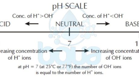
pH refers to the concentration of hydrogen ions in solution. The lower the pH the more hydrogen
ions present. The higher the pH the fewer hydrogen ions present
pH scale: Concentration of Hydrogen ions
The acidity and alkalinity of a solution is extremely important in Reverse Osmosis water treatment due to factors such as membrane degradation, membrane cleaning, etc. This is because certain chemical reactions will only take place at specific pH values.
The term pH is used to describe whether a solution is alkaline or acidic. The concept of acidity and alkalinity may best be described by going back to the dissociation constant.
Looking at the exponent on the concentration of Hydrogen H+ ion, we see that as the H+ concentration goes up (and OH- concentration goes down) we get a smaller negative number. Likewise, as Hydroxide OH- concentration goes up (and H+ concentration goes down) we get a larger negative number.
[H+] x [OH-] = 1.0 x 10^-14
With addition of acid (H+)
1.0 x 10^-5 x 1.0 x 10^-9 = 1.0 x 10^-14
With addition of base (OH-)
1.0 x 10^-9 x 1.0 x 10^-5 = 1.0 x 10^-14
Exponent changes with changes in H+ and OH- concentrations
Taking this into consideration, scientists learned that a more convenient way to describe the hydrogen ion concentration of a solution is to take the negative logarithm of the hydrogen ion concentration. A logarithm is the exponent to which a base number is raised to produce a given number. NOTE: We will usually use a base of 10.
EXAMPLE: The log (logarithm) of 100 is 2: Ten raised to the power of 2 (102).
EXAMPLE: The log of 127 is 2.1 (On a scientific calculator, enter 127, then push the [LOG] key).
| NUMBER | LOG | NUMBER | LOG |
| 1 = 1 X 10^0 | 0 | 1.0 = 1 X 10^0 | 0 |
| 10 = 1 X 10^1 | 1 | 0.1 = 1 X 10^-1 | -1 |
| 100 = 1 X 10^2 | 2 | 0.01 = 1 X 10^-2 | -2 |
| 1000 = 1 X 10^3 | 3 | 0.001 = 1 X 10^-3 | -3 |
| 10000 = 1 X 10^4 | 4 | 0.0001 = 1 X 10^-4 | -4 |
| 100000 = 1 X 10^5 | 5 | 0.00001 = 1 X 10^-5 | -5 |
| 1000000 = 1 X 10^6 | 6 | 0.000001 = 1 X 10^-6 | -6 |
| 10000000 = 1 X 10^7 | 7 | 0.0000001 = 1 X 10^-7 | -7 |
The symbol for the negative log is “p”. Therefore, the negative log of the Hydrogen ion concentration is “pH”. Table below lists several hydrogen ion concentrations, hydroxide concentrations, and the corresponding pH and pOH. Note that a pH of 7 is neutral because the Hydrogen ion concentration [H+] and hydroxide concentration [OH-] are the same. As [H+] increases, pH decreases.
| H+ (mol/L) | OH- (mol/L) | ||||
| Decimal | SN | pH | Decimal | SN | pOH |
| 0.00000000000001 | 1 X 10^-14 | 14 | 1.0 | 1 X 10^0 | 0 |
| 0.0000000000001 | 1 X 10^-13 | 13 | 0.1 | 1 X 10^-1 | 1 |
| 0.000000000001 | 1 X 10^-12 | 12 | 0.01 | 1 X 10^-2 | 2 |
| 0.00000000001 | 1 X 10^-11 | 11 | 0.001 | 1 X 10^-3 | 3 |
| 0.0000000001 | 1 X 10^-10 | 10 | 0.0001 | 1 X 10^-4 | 4 |
| 0.000000001 | 1 X 10^-9 | 9 | 0.00001 | 1 X 10^-5 | 5 |
| 0.00000001 | 1 X 10^-8 | 8 | 0.000001 | 1 X 10^-6 | 6 |
| 0.0000001 | 1 X 10^-7 | 7 | 0.0000001 | 1 X 10^-7 | 7 |
| 0.000001 | 1 X 10^-6 | 6 | 0.00000001 | 1 X 10^-8 | 8 |
| 0.00001 | 1 X 10^-5 | 5 | 0.000000001 | 1 X 10^-9 | 9 |
| 0.0001 | 1 X 10^-4 | 4 | 0.0000000001 | 1 X 10^-10 | 10 |
| 0.001 | 1 X 10^-3 | 3 | 0.00000000001 | 1 X 10^-11 | 11 |
| 0.01 | 1 X 10^-2 | 2 | 0.000000000001 | 1 X 10^-12 | 12 |
| 0.1 | 1 X 10^-1 | 1 | 0.0000000000001 | 1 X 10^-13 | 13 |
| 1.0 | 1 X 10^-0 | 0 | 0.00000000000001 | 1 X 10^-14 | 14 |
- Published in Water Chemistry, Water Treatment
What is Dissociation Constant Definition
Dissociation Constant demonstrates the maximum range to which an element or substance would dissociate into ions. The Dissociation Constant referred to as “K” is equal to the product of the concentrations of the corresponding ions:
K = [H+] x [OH-]
The dissociation constant for a compound such as sodium chloride is very large since the ions are almost totally dissociated (exist as separate cations and anions). Dissociation constants for compounds which do not readily dissociate (separate) are small.
Highly Soluble Salts <——-> Large Dissociation Constant
Slightly Soluble Salts <——> Small Dissociation Constant
Most ionic compounds will dissociate to some extent. Even water will slightly dissociate as described by the equation below.
H2O —-> (H+) + (OH-)
The dissociation constant for water is found by multiplying the concentrations of the hydrogen ion (H+) and the hydroxide ion (OH-). The brackets in the equation indicate that we are dealing with concentrations expressed in molarity. Scientists found that the product of concentration of the two ions is 1.0 x 10⁻¹⁴ at standard conditions.
K = [H+] x [OH-] = 1.0 x 10^-14
If we are dealing with pure water, we know that the concentration of H+ and OH- must be the same since one of each is required to make a water molecule.
[H+] = [OH-]
Since,
(H+) + (OH-) —–> H2O
Therefore, if the concentrations of the ions multiplied together are equal to 1.0 x 10^-14 and the concentrations of each ion are the same, we know that the concentration of each ion is 1.0 x 10^-7. Remember, when we multiply numbers with exponents, we add the exponents together.
[H+] x [OH-] = 1.0 x 10^-14
1.0 x 10^? x 1.0 x 10^? = 1.0 x 10^-14
[H+] and [OH-] are equal:
[H+] = [OH-] = 1.0 x 10^-14
1.0 x 10^-7 [H+] x 1.0 x 10^-7 [OH-] = 1.0 x 10^-14
If we add some hydrochloric acid (HCl) to the pure water, the concentration of hydrogen ions will increase since HCl is almost completely dissociated.
HCl + H2O —–> H+* + Cl- + H2O
*Concentration of H+ is increased by the addition of HCl
As the concentration of hydrogen ions increases, the concentration of hydroxide ions decreases. This is because the dissociation constant (product of the H+ concentration multiplied by the OH- concentration) for water does not change. It is a basic chemical characteristic just like density, boiling point, freezing point, etc.
[H+] x [OH-] = 1.0 x 10^-14
As the concentration of H+ goes up, the negative exponent on the concentration value goes down. In our example below, it goes from -7 to -5. The hydroxide exponent therefore must go from -7 to -9. Remember, the dissociation constant does not change. The product of the two concentrations (sum of the exponents) must always equal -14.
Example:
Pure Water
1.0 x 10^-7 x 1.0 x 10^-7 = 1.0 x 10^-14
With the addition of acid
1.0 x 10^-5* x 1.0 x 10^-9 = 1.0 x 10^-14**
*This number is larger due to the addition of acid.
**This number must remain the same.
In the same manner, if we add sodium hydroxide (NaOH) to pure water, the OH- concentration will increase. If the OH- concentration increases, the H+ concentration must decrease.
Now we can see that with water we can have one of three conditions. First, we can have a condition in which there are an equal number of H+ and OH- ions. Water in this state is said to be neutral. Second, we can have a condition in which we have more H+ than OH- ions. This condition is called acidic. Third, we can have a condition in which there are more OH- than H+ ions. This condition is called basic or alkaline.
[H+] > [OH-] —–> Acidic
[H+] = [OH-] —–> Neutral
[H+] < [OH-] —–> Alkaline
- Published in Water Chemistry, Water Treatment
What is a Cartridge Filter Definition
A Cartridge filter is a fine microfilter of nominal size from 1 to 25 um (micron) made of thin plastic fibers or other fine filtration media that is installed around a central tube to form a standard-size cartridge. Cartridge Filters are often used as the only screening device between the intake wells and the Reverse Osmosis system. This is in case of brackish and seawater desalination plants with well intakes producing high-quality source water. Cartridge filters are RO membrane protection facilities rather than screening devices; the main purpose they serve is to capture particulates in the pretreated source water that may have passed through the upstream pretreatment systems in order to prevent damage or premature fouling of the RO membranes.
Although wound (spun) polypropylene filter cartridges are most commonly used for seawater and brackish water applications. Other types, such as melt-blown or pleated cartridges of other materials have also found application. Standard cartridge filters for RO desalination plants are typically 101.6 to 1524 cm (40 to 60 in.) long. And are installed in either horizontal or vertical pressure vessels (filter housings). Cartridges are rated for removal of particles of 1, 2, 5, 10, or 25 um, with the most frequently used size being 5 um.
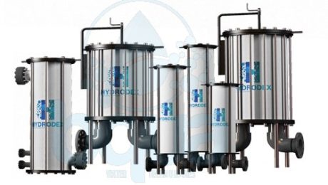
Fig. 1: Example on Cartridge Filter Housing Manufacturer: Hydrodex Filter Housings
It is useful to mention that Hydrodex is one of the market leaders in the filtration industry. Hydrodex manufactures a premium cartridge filter made of Glass Reinforced Polymer (GRP).
Cartridge Filter Planning and Design Considerations
Cartridge filters are typically installed downstream of the granular media filtration system. That is in case such a system is used for pretreatment to capture fine sand, particles, and silt that may be contained in the pretreated water. When the source seawater is of very high quality – a silt density index (SDI) below 2 – and does not need particulate removal by filtration prior to desalination. In this case cartridge filters are used as the only pretreatment device. Serving as a barrier to capture fine silt and particulates that can occasionally enter the source water during the start-up of intake well pumps or due to failure of intake equipment or piping.
Cartridge Filter in Horizontal Orientation
A typical indication of whether the pretreatment system of a given desalination plant operates properly is the SDI reduction through the cartridge filters. If the pretreatment system performs well, then the SDI of the source water upstream and downstream of the cartridge filters is approximately the same. If the cartridge filters consistently reduce the SDI of the filtered source water by over 1 unit. This means that the upstream pretreatment system is not functioning properly. Sometimes the SDI of the source water increases when it passes through the cartridge filters. This almost always occurs because the cartridge filters have not been designed properly or are malfunctioning and providing conditions for growth of biofouling microorganisms on and within the filters.
A frequently debated question is whether cartridge filters are needed downstream of MF or UF membrane pretreatment systems. Taking into consideration that the cartridge filter pores are one to two orders of magnitude larger than those of the membrane filters. The answer to this question is highly dependent on the quality of the pretreatment membrane’s fiber material. And the type of flow pattern through the pretreatment system.
For UF or MF filtration systems that have a direct flow-through pattern. Where the desalination plant feed pumps convey water directly through the membrane pretreatment system without an interim pumping. The pretreatment membranes are more likely to be exposed to pressure surges. If the fiber material of the pretreatment membranes is weak and breaks easily under pressure surge conditions, the pretreatment system is more likely to experience fiber breaks. Broken membrane fibers will release small amounts of particles into the RO feed water. Which could cause accelerated membrane fouling unless it is captured by cartridge filtration.
In addition, if the broken membrane fibers release sharp particles contained in the source water, these particles could also damage the RO membranes. Sharp broken-shell particles may find their way into the UF or MF pretreated water if shellfish plankton contained in the source water passes through the microscreens. Grows to adult shellfish organisms (e.g., barnacles) on the walls of the pretreatment system feed pump station. And releases portions of shells that have been broken into small, sharp particles by the feed pumps.
The shell particles will be pressurized onto the UF/MF membrane filter fibers, causing punctures and ultimately entering the filtered flow. In such cases, the use of cartridge filters downstream of the membrane pretreatment system is a prudent engineering practice. Cartridge filters are operated under pressure, and the differential pressure across them is monitored to aid in determining when filter cartridges should be replaced. In addition, valved sample ports should be installed immediately upstream and downstream of the cartridge filter vessels for water quality sampling and monitoring (including SDI field testing).
Cartridge filtration systems are designed for hydraulic loading rates of 0.2 to 0.3 L/s per 250 mm (3 to 5 gal/min per 10 in.) of length. Additional filtration capacity is normally provided to allow replacement of cartridges without interruption of water production. Pressure vessels are typically constructed of duplex stainless steel for seawater RO installations.
The pressure drop across a clean cartridge filter is usually specified as less than 0.2 bar (2.8 lb/in2). Commonly, cartridges are replaced when the filter differential pressure reaches 0.7 to 1.0 bar (10.1 to 14.5 lb/in2). The operational time before replacement depends on the source water quality and the degree of pretreatment. Typically, a cartridge filter replacement is needed once every 6 to 8 weeks. However, if the source seawater is of very good quality cartridge filters may not need replacement for 6 months or more.
For RO systems where sand in the feed water might be anticipated. Rigid meltblown cartridges or cartridge filters with single open ends and dual O-rings on the insertion nipple. Rather than conventional cartridges with dual open ends, are commonly used. The single-open-end insertion filters have positive seating and an insertion plate. Which does not allow deformation of the filter cartridge under pressure caused by sand packing. Double-open-end cartridge filters are held in place by a spring-loaded pressure plate.
Design Example of a Cartridge Filter
This example presents the sizing and configuration of the cartridge filtration system for a 40,000 m3/day (10.6 mgd) seawater desalination plant. With a total plant seawater intake flow of 98,440 m3/day (26 mgd).
| Design feed flow, Qin | 98,440 m3/day = 1140 L/s |
| Cartridge filter material | Pleated polypropylene |
| Cartridge filter size | 5 um (micron) |
| Cartridge filter length, Lcf | 1016 mm (40 in.) |
| Selected design loading rate, DLR | 0.25 L/s per 250 mm |
| Number of cartridge filters needed | Qin/[DLR x (Lcf/250)] (8.1) = 1140/[0.25 x (1016/250)] = 1122 |
| Number of cartridge vessels | 6 (selected to match RO trains) |
| Cartridge vessel material | Glass-reinforced plastic |
| Number of filter cartridges per vessel | 1122/6 = 187 (selected 180) |
| Actual cartridge filter loading rate | 1140/[180 x 6 x (1016/250)] = 0.26 L/s per 250 mm (4.2 gal/min per 10 in.) |
In summary, the cartridge filtration system for the 40,000 m3/day (10.6 mgd) desalination plant will consist of six cartridge vessels. Each of which will contain 180 cartridge filters of size 5 μm and length 40 in.
- Published in Technology, Water Treatment
What is Reverse Osmosis (RO) Definition
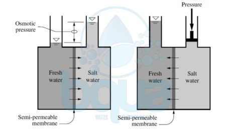
Reverse osmosis (RO) is basially the reverse of the osmosis process. Scientists found that all that is required to reverse the process of osmosis is a suitable semipermeable membrane and applying a pressure to the concentrated salt solution above the applied and osmotic back-pressures, thereby forcing pure water through the semipermeable membrane. In other words, reverse osmosis is the process where water containing inorganic salts (minerals), suspended solids, soluble and insoluble organics, aquatic microorganisms, and dissolved gases (collectively called source water constituents or contaminants) is forced under pressure through a semipermeable membrane. Semipermeable refers to a membrane that selectively allows water to pass through it at much higher rate than the transfer rate of any constituents contained in the water. Learn more about pressure driven membranes here. If water of high salinity is separated from water of low salinity via a semipermeable membrane, a natural process of transfer of water will occur from the low-salinity side to the high-salinity side of the membrane until the salinity on both sides reaches the same concentration. This natural process of water transfer through a membrane driven by the salinity gradient occurs in every living cell; it is known as osmosis.
The hydraulic pressure applied on the membrane by the water during its transfer from the low-salinity side of the membrane to the high-salinity side is termed osmotic pressure. Osmotic pressure is a natural force similar to gravity and is proportional to the difference in concentration of total dissolved solids (TDS) on both sides of the membrane, the source water temperature, and the types of ions that form the TDS content of the source water. This pressure is independent of the type of membrane itself. In order to remove fresh (low-salinity) water from a high-salinity source water using membrane separation, the natural osmosis-driven movement of water must be reversed, i.e., the freshwater has to be transferred from the high-salinity side of the membrane to the low-salinity side. For this reversal of the natural direction of freshwater flow to occur, the high-salinity source water must be pressurized at a level higher than the naturally occurring osmotic pressure.
If the high-salinity source water is continuously pressurized at a level higher than the osmotic pressure and the pressure losses for water transfer through the membrane, a steady-state flow of freshwater from the high-salinity side of the membrane to the low-salinity side will occur, resulting in a process of salt rejection and accumulation on one side of the membrane and freshwater production on the other. This process of forced movement of water through a membrane in the opposite direction to the osmotic force driven by the salinity gradient is known as reverse osmosis (RO).
The rate of water transport through the membrane is several orders of magnitude higher than the rate of passage of salts. This significant difference between water and salt passage rates allows membrane systems to produce freshwater of very low mineral content. The applied feed water pressure counters the osmotic pressure and overcomes the pressure losses that occur when the water travels through the membrane, thereby keeping the freshwater on the low-salinity (permeate) side of the membrane until this water exits the membrane vessel.
Osmosis and Reverse Osmosis Process
The salts contained on the source water (influent) side of the membrane are retained and concentrated; they are ultimately evacuated from the membrane vessel for disposal. As a result, the RO process results in two streams—one of freshwater of low salinity (permeate) and one of feed source water of elevated salinity (concentrate, brine or retentate), as shown in the figure above. While semipermeable RO membranes reject all suspended solids, they are not an absolute barrier to dissolved solids (minerals and organics alike). Some passage of dissolved solids will accompany the passage of freshwater through the membrane. The rates of water and salt passage are the two key performance characteristics of Reverse Osmosis membranes.
Reverse Osmosis Process Drawing
- Published in Technology, Water Treatment
What is Turbidity Definition
Turbidity is a parameter which measures the content of particulate foulants in the reverse osmosis feed water source. Turbidity can also be defined as the measurement of the light scattering properties of particles in suspension. The instrument used to measure turbidity is called a turbidimeter or turbidity meter.
The principle of turbidity meters is that suspended particles will block or reflect light. There are several different types of turbidity meters, but they are all based on the principle of particles blocking or reflecting light. Let’s look at reflected light first.
If there are no particles suspended in a sample, light will pass through the sample in a straight line. If a photocell (photoreceptor) is located at 90 degrees to the light path, no light will reach the photocell and the turbidity will read zero.
If particles present in a sample, the light will be reflected off of the surfaces of the particles and will be scattered at different angles. A photoreceptor at 90 degrees from the source of light will pick up light that is scattered and a turbidity measurement greater than 0 will be obtained.
The unit of measurement for turbidity is the NTU or the JTU or the FTU. There is no correlation between NTU and JTU and FTU. The term nephelometric indicates that this is a light-interference analytical technique. NTU is the measurement unit for light scattering. Some on-stream turbidity meters also use the light-scattering principle. A common one is called the surface scatter turbidimeter.
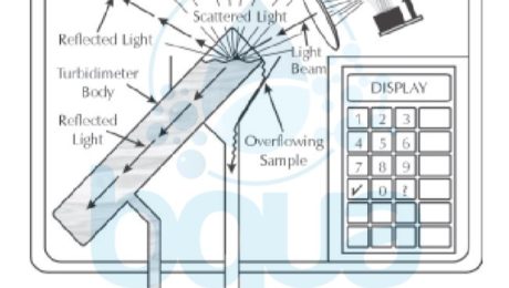
For a surface-scatter turbidimeter, the sample with suspended particles is passed up through a tube. A light source is shining on the surface of the liquid as it flows over the top of the tube. A photocell is located above the surface of the water. If there are no particulates in the water, the light beam is absorbed by the black tube and the black interior of the enclosure. If they are present, they scatter light as they surface (This is why this technique is called surface-scatter). The photocell picks up the scattered light and displays the reading in NTU.
There is another type of turbidimeter which doesn’t measure the light scattered but rather the reduction in transmitted light. In this case the full beam is received by the photocell. Full-beam reception equates to clean water and no turbidity.
 Â
If particles are present, less light reaches the photocell. This, then, is displayed as a turbidity reading, in JTU (Jackson Turbidity Unit, named after the man who created the standard candle which was originally used as the source of the light). Figure below illustrates particulates in the sample scattering, and therefore blocking, the light beams.
The turbidity level in the source of water is indicative of the content of clay, silt, suspended organic matter, and microscopic aquatic life. Such as phyto- and zooplankton. It is expressed in Nephelometric Turbidity Units (NTU) and Formazin Nephelometric Unit (FNU). The turbidity of open ocean and surface brackish water can vary between 0.1 and several hundred NTU, although under normal dry weather conditions, it is typically between 0.5 and 2.0 NTU. Rain events, algal blooms, storms, snow melt, river discharges, and human activity (such as wastewater discharges, ship traffic, etc.) can cause significant turbidity increases and variations. Usually, water that is saline with a turbidity below 0.05 NTU causes very low particulate fouling of the reverse osmosis membrane. Most RO membrane manufacturers have a maximum feed raw water turbidity of 1.0 NTU, although this level is relatively high in practical terms. Usually, filtered water turbidity below 0.1 NTU is desirable.
Although turbidity is a good measure of the overall content of particulates in the source water, on its own it is not an adequate parameter to characterize water’s potential for particulate or other fouling. Turbidity measurement does not provide information regarding the type and particle size in the source feed water and does not measure the constitution of dissolved organic and inorganic foulants. The size of particles contained in the source water matters because RO membrane feed and concentrate spacers, through which the saline raw water is distributed inside the membranes, are of limited width (typically 0.7 to 0.9 mm).
Even with these problems, turbidity measurements can be valuable trending indications for monitoring RO unit feed water. Most manufacturers require that the feed water to an RO unit be less than 1.0 NTU. Turbidity is almost always measured on feed waters which are processed through a clarifier. Clarifiers are usually found at facilities with a surface water source and no prior municipal treatment. In this case turbidity is frequently measured before and after the clarifier to monitor the performance of the clarifier. In a few cases, turbidity is measured before and/or after a multimedia filter to monitor performance of this piece of equipment. Turbidity or TSS measurements alone are insufficient to tell us about the fouling potential of our feed water. They must be used in conjunction with SDI (Silt Density Index).
- Published in Water Chemistry, Water Treatment
Concentration Polarization
If there are fouling feed water colloidal silica particles, these sub-micron particles will not be trapped in feed water spacer. They may be deposited evenly on the surface of the membrane, causing a problem in all stages. Usually the colloidal particles create more of a last stage problem. Colloidal fouling occurring in the last stage is likely due to agglomeration of sub-micron particles into larger fouling particles due to surface charge neutralization of the particles by double- and triple-charged cations concentrated at the surface of the Reverse Osmosis RO membrane. Due to concentration polarization, colloidal fouling is more likely at the surface of the membrane and in the rear end of a Reverse Osmosis System.
concentration polarization boundary layer on RO membrane surface
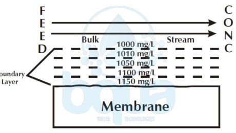
Whenever water flows past a solid, there is some attraction and adhesion between the water and the solid. Adhesion between the water and the solid surface causes the water molecules closest to the surface to be stationary relative to it. The farther from the surface water molecules are, the less attraction and adhesion, and therefore the more velocity relative to the surface. Right at the membrane surface, there is no tangential flow. This is the boundary layer When tiny particles deposit on the membrane surface, there is no tangential flow to sweep them off.
concentration polarization on reverse osmosis membrane
Additionally, the flow of water through the RO membrane, when the high pressure pump is on, will tend to hold them there Not only are feed water particles deposited on the membrane in this way. They may also be grown there. This is likely caused by concentration polarization. Concentration polarization is a function of the boundary layer. It refers to an increased salt concentration at the RO membrane surface. A portion of the feed water passes through the boundary layer and through the membrane.
The water passes through the membrane. The dissolved components do not readily pass through the membrane. The dissolved components, therefore, are left behind at the membrane surface. This causes the salt concentration (TDS, Total Dissolved Solids concentration) to be higher at the membrane surface If the boundary layer had tangential flow and was turbulent, the incoming feed water would mix up the boundary layer and the boundary layer would have the same concentration as the bulk stream.
concentration polarization and total dissolved salts
The boundary layer, however, has no tangential flow. The salts concentrate at the surface. Fortunately, the dissolved substances can diffuse away from the membrane. Recall that diffusion is the movement of dissolved substances from higher concentration to lower concentration. So if we could look into the boundary layer, we would see that, due to diffusion, the salt concentration diminishes from the surface of the membrane to the top of the boundary layer.
At the top of the boundary layer, the concentration is the same as the bulk stream The higher the water flux through the membrane, the more salts collect at the membrane surface, and therefore the higher the salt concentration at the membrane surface. Typically the TDS at the membrane surface is 10% – 15% higher than that measured in the bulk stream. If water flux is increased, a higher TDS will occur at the surface. As we will see below, concentration polarization not only impacts dissolved solids. It may also affect suspended solids.
- Published in Water Treatment
Semipermeable Membrane Definition
Semipermeable membrane is a thin, soft, pliable sheet of material that allows certain substances to freely pass through it while restricting the passage of other substances. In the water treatment field, a semipermeable membrane allows water to pass freely while restricts the passing of dissolved materials.
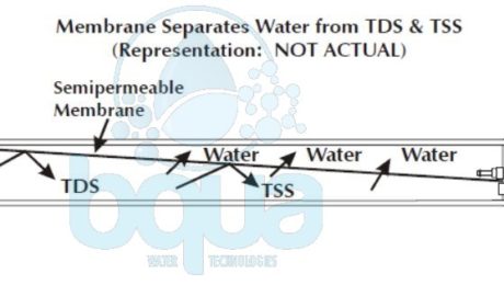
Water passes through a semipermeable membrane into a solution of higher salt concentration. This phenomenon is called Osmosis. The semi-permeable membrane is a material through which water may pass, but prohibits the traveling of nearly everything else. Because of pressurized feed water enters each pressure vessel, a portion of the incoming water goes through the semipermeable membrane. The semi-permeable membrane selectively restricts the passage of suspended and dissolved elements in the raw water.
Semipermeable membrane separating TDS and TSSÂ
The incoming supply water and the dissolved and suspended substances which don’t pass throughout the semipermeable membrane go to waste. One stream enters an RO system and two streams exit. The permeate is the water stream and small amount of TDS which goes through the Semipermeable Reverse Osmosis membrane. While the concentrate is the waste stream containing the water and elements which don’t go through the semipermeable membrane. The concentrate is simply concentrated incoming stream of water. The concentrate contains the TDS and the TSS that are not allowable to pass through the semipermeable membrane.
Read more about the RO Membrane.
- Published in Technology, Water Treatment
Water Treatment Power Plant:
There are many power generation plants around the world. It takes a lot of cooling water and it takes a lot of high purity water created in sophisticated water treatment power generation system to produce electricity. We need to know how electricity is made in order to understand the water treatment for boiler feed water properties and also cooling tower feed water.
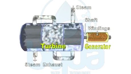
We’ve all seen electric motors, electricity goes into the winding of the motor and causes the shaft to turn. Power generation is the reverse of the motor, if a shaft is turned within the winding, electricity exits the windings.
electricity causes shaft in motor to turn
In a power generation plant, windings section is called the generator. The shaft inside of the windings is attached to a shaft inside of the turbine section. And within the turbine are sets of fins. Steam enters the turbine and passes through the fins causing the shaft to turn. This results in the production of electricity from the generator.
water treatment power plant electricity generation
The steam must be very high purity. If the steam has contaminants like Silica present, they can scale out on the surface of the blades causing an imbalance that will eventually destroy the turbine. The high purity steam is produced in the boiler. When liquid water is heated sufficiently, steam is produced. A boiler is an efficient way of boiling water and producing steam. This is why boiler water treatment along with cooling tower water treatment are very important and critical in the water treatment power generation.
The most commonly used water treatment power plant scheme for treating boiler feed water is by using a reverse osmosis system. Along with a mixed bed resin, we guarantee a complete removal of any contaminants that can cause scaling inside the turbine. Visit BQUA water treatment products page to learn more about our reverse osmosis system and its capabilities.
- Published in Water Treatment
What is Bioflocculation
Bioflocculation is marked as an advanced, non-chemical, microbial based pre-treatment technology. The technology of bioflocculation uses a novel Rapid Sand Filters RSF configuration together with an extremely porous volcanic Tuff filtration medium. This provides an enlarged surface area for microbial development and biofilm reproduction and propagation.
In the majority of large scale seawater reverse osmosis SWRO plants, the main pre-treatment method is based on granular multimedia filters. This is also known as rapid sand filters (RSF). The vast use of RSF is mainly the result of their simplicity, low energy consumption, and low maintenance and operational costs. Regardless the need to use coagulants such as Alum or ferric sulfate to feed water. RSFs main application is to remove suspended solids greater than 0.35mm in diameter from the feed water stream. It also lowers the level of SDI to around 4. Studies made on RSF also shows that such filters are capable of reducing the levels of suspended particles. Also reducing dissolved TOC, chlorophyll a and transparent exopolymeric particles (TEP). In operation, when a RSF becomes overloaded with particles, a backwash procedure applies. Backwash flushes out the suspended living and non-living particles that has accumulated in the filter bed.
A pilot for Rapid Bioflocculation Filter (RBF) was constructed with two fiberglass columns (each of 6m in height and 1m diameter). It is an upward flowing Bioflocculator (BF) unit, packed with 3m natural porous volcanic Tuff medium (by Tuff Merom Golan). And downward flowing, mixed-media bed filter (MBF) consisting of 80 cm Filtralite (by Filtralite Co.) over 80cm sand. The pilot scale effectiveness is monitored by measuring the efficiency of the removal from the feed water. Key factors were related to membrane clogging; silt density index (SDI), turbidity, chlorophyll a (Chl a) and transparent exopolymer particles (TEP). It is mainly designed to optimize microbiological activity within the filter bed. The results from one year of operation of a large-scale pilot, dual-stage granular filter, indicate that this pretreatment technology with no addition of coagulants. Also no other chemicals gave results equivalent to a conventional RSF with prior chemical (Fe2[SO4]3) treatment.
Bioflocculation Volcanic Tuff Media
Volcanic Tuff grain sizes ranged between 3 and 5 mm in diameter, with a bulk density of 2110 kg/m3 and porosity relative to volume of 26.7%. The total pore area was 20 m2, with extremely wide pore size ranges (0.05 to >10 mm). median pore diameter was 0.75 mm with a characteristic pore length of 62 mm. The large range of pore sizes enabled a wide diversity of microorganisms to colonize the medium pores as a result of reduced shear forces.
Conventional pre-treatment procedures in seawater reverse osmosis SWRO rely mainly on RSF. The process mechanically removes suspended solids greater than 0.35 mm in diameter formed upstream. This occurs after the addition of chemicals in a coagulation and flocculation step. When RSF is overloaded with particles as indicated by high differential pressure across the filter, backwash procedure is carried out. Backwash is mainly flushing and cleaning the filter bed. The same procedure should be taken with RBF filters.
The study made on this new discovery has demonstrated the potential of a biologically-based pre-treatment for SWRO desalination. The results are based on a year-long study. It shows a comparable performance by a large pilot, two-stage, granular Rapid Bioflocculation Filter (RBF) consisting of a Bioflocculator unit with volcanic Tuff medium. This is followed by a Mixed Bed Filter with no prior chemical additives and a standard RSF operating with addition of chemical flocculant [Fe2(SO4)3] upstream. This was at the Hadera SWRO facility in Israel. Much of the effective performance of the RBF is due to the bioflocculation process which occurs within the Tuff medium.
Some biodegradation may also take place. But because of rapid flow rates through RBF, this is unlikely to be a major factor in the filtration process. The study shows that during normal operation there is continuous microbial growth and development of a biofilm layer of organisms. The growth is within an organic matrix that effectively retains different types of colloidal and particulate matter. When shear forces increase during flush cleaning cycles, some of this bio-aggregated material are released into the BF filtrate as bioflocs. These bioflocs are large enough and are mechanically retained with high efficiency by the MBF.
The bioflocculation process that occurs in the first stage of the RBF depends on the metabolism of an extensive, biological food web. It involves different populations of bacteria, archaea, cyanobacteria, protozoa, and even crustaceans and marine worms. It is noteworthy that this kind of microbial environment only develops on the highly porous Tuff grains of the BF and not on the MB filter media.
Conclusion on bioflocculation study
In conclusion, the study demonstrates that with suitable filter bed media and some design modifications, it is possible to construct a rapid granular filter. The RGF achieves effective largescale pre-treatment filtration equivalent to that of currently operating RSF. But without the need for prior chemical coagulation. The research suggest that this approach of using bioflocculation without chemical additives could have considerable potential. It could act as an alternative to conventional RSF pre-treatment for large seawater reverse osmosis SWRO facilities.
- Published in Technology, Water Treatment
What is Molecular Geometry ?
Molecular Geometry is basically the three dimensional arrangement / shape / structure of atoms that form a molecule. When molecules are formed by chemical bond which means atoms bonding together, suborbitals involved in the bond or bonds create different molecular shapes depending on many factors.
For example, the water molecules are not linear, a water molecule is actually ‘V’ shaped and the angle formed between the two Hydrogen atoms and the Oxygen atom is approximately of 105° degrees.
molecular geometry of water molecule hydrogen oxygen
When we draw molecules in two dimensions, we most of the time think that these molecules are flat. But in fact they exist in several different shapes and forms.
The Chemical Composition and the Molecular Geometry of a molecule is what mainly determine the properties of the molecule. Such as taste, boiling point, magnetism, dynamic, polarity, color, and all other properties.
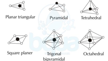
Molecular Geometry and different types of molecular structures:
-
Linear Molecular Geometry
In a Linear Molecular Geometry structure, atoms are bonded together to form a straight line. Bonding angles are of 180° degrees and as an example is the Carbon Dioxide (CO2) and the Nitric Oxide (NO).
-
Planar Triangular –Â Trigonal Planar Molecular Geometry
Trigonal Planar Molecualr Geometry is formed when a compound has an atom at the centre attached to three other atoms in an arrangement that looks like a triangle around the central atom. The four atoms are on the same line and flat on a plane.
-
Trigonal Pyramidal Molecular Geometry
Trigonal Pyramidal Molecular Geometry is obviously shaped like a pyramid with a base that looks like a triangle. The Trigonal Pyramidal structure looks like the Tetrahedral Molecular Geometry, pyramidal structures need three dimensions so that they can fully separate electrons. An example on the Trigonal Pyramidal orientation is Ammonia (NH3).
-
Tetrahedral Molecular Geometry
Tetra means four and tetrahedral means basically a solid or pyramid that has four sides. Tetrahedral Molecular Geometry is formed when one central atom has four bonds with four atoms all at once forming a pyramid-like shape with four sides. As per the VSEPR which is the Valence Shell Electron Pair Repulsion theory, the bond angles between the atoms in the tetrahedral orientation are approximately 109.47°. An example of the Tetrahedral Molecular Geometry is methane (CH4).
-
Square Planar Molecular Geometry
The Square Planar Molecular Geometry is formed when a central atom has four bonds and two lone pairs. Xenon Tetrafluoride (XeF4) is an example of the Square Planar structure, it is made up of six equally spaced orbitals arranged at 90° degrees angles. Which forms an octahedral shape. Two orbitals contain lone pairs of electrons on opposite sides of the central atom. And the other four atoms are bonded to the central atom making the molecule a square planar structure.
-
Trigonal Bipyramidal Molecular Geometry
The Trigonal Bipyramidal Molecular Geometry happens when the central atom is connected to five atoms forming five bonds and no lone pairs. Three out of the five bonds are created along the atom equator forming 120° degrees angles while the remaining two are formed on the atom axis. An example on the Trigonal Bipyramidal Molecular Geometry is the Phosphorus Pentachloride (PCl5).
-
Octahedral Molecular Geometry
Octa means eight and Octahedral Molecular Geometry means a pyramid or solid that has eight sides or faces. Octahedral structure has six bonded atoms forming 90° degrees angles between them. An example on the Octahedral Molecular structure is Sulfur Hexafluoride (SF6).
Molecular Shapes and different types of molecular structures
- Published in Water Chemistry, Water Treatment
What is a Covalent Bond
Atoms can bond by sharing electrons in their outermost orbitals and thus giving them the privilege of having a full outermost orbital. For example, the element Hydrogen exists as H2 molecule consisting of two atoms of Hydrogen atom. A covalent bond is simply the force between two atoms resulting from the sharing of electrons in the outermost orbital. Therefore a covalent bond attracts two atoms very close to each others because both atoms share the same electrons in their outermost orbitals.
hydrogen gas formed by covalent bond sharing electron between two hydrogen atoms
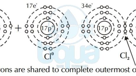
The case of Hydrogen cannot be an ionic bond. That is because Hydrogen ions each have the same charge and therefore are not attracted to one another. This is why a covalent bond happens only when two atoms have a difference in electronegativity of > or = 0.9. Instead, electrons are shared between the atoms to fill the outermost orbital. This type of bond is called a covalent bond. Two atoms of chlorine (Cl0) share a pair of electrons to form chlorine gas (Cl2).
electron shared covalent bond chlorine atom forming chlorine gas
Some molecules formed by covalent bonds may still give up or acquire one or more electrons resulting in a net positive or negative charge. These molecules are called molecular ions.
A covalent bond is very strong. The energy needed to break it is bigger than the thermal energy existing at 25°C which is room temperature. The thermal energy at 25°C is <1 kCal/mole kilo calorie per mole, while to break a typical Carbon covalent bond in an Ethane molecule we need about 83 Kilocalorie per mole.
Properties of molecules defined by covalent bond
While a central atom in a molecule attracts other atoms by covalent bonds, the bonds between these atoms are forming particular angles between them. The force of repulsion among these atoms and particularly the outermost electrons is what shape and determine the angles degrees. The angles and the shape formed is what gives the molecule its properties and shape. An example is the angle formed between Oxygen and Hydrogen atoms in a water molecule, an angle of 105°. You can read about the molecular geometry.
When atoms formed in a covalent bond have the same or very close electronegativity – typically less than 0.9 – the bond (the force of attraction) is equal between electrons since they’re almost identical. This kind of bond is called a non-polar bond. Carbon-Carbon and Carbon-Hydrogen bonds (also called Hydrocarbon) is an example on non-polar bonds.
A polar bond occurs when the difference in electronegativity between two atoms are more than or equal to 0.9. In a polar bond, there’s a partial negative charge (δ−) and a partial positive charge (δ+). This is the case in a water molecule H2O. The bond between Oxygen and Hydrogen is polar since difference in electronegativity is 1.2. (Electronegativity of Oxygen is 3.4 and Electronegativity of Hydrogen is 2.2).
- Published in Water Chemistry, Water Treatment
Electron configuration:
The electron configuration is simply the orientation of electrons about the nucleus of the atom. It is known that the atom structure consists electrons, protons and neutrons. An electron has a negative charge, a proton has a positive charge and is in the nucleus with neutrons. Neutrons have neutral charges (non-charged particles).
In a neutral atom, the number of electrons that electron configuration forms are always equal to the number of protons inside the nucleus. The neutron does not contribute to the electrostatic force which is the force that holds the atom together.
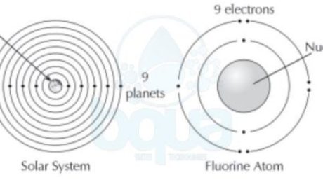
It was found that in the atom structure, electrons tend to orient themselves in a particular fashion. This orientation is called the electron configuration. When atoms get larger and gain more electrons, electrons will exist in particular orbits around the nucleus. A living example of such practice is how each planet in our solar system circles the sun in its own orbit.
electron configuration electrons orient themselves around nucleus protons earth planets
In the electron configuration, we find that more than one electron may exist in the same orbit around the nucleus. The first orbital may contain one to two electrons. While the second orbital may contain up to eight electrons. Each subsequent orbital can hold more and more electrons.
Equation for electron configuration
The equation for the number of electrons in each energy level is:
# of electrons = 2(n)^2 Â where “n” is the nth level
For example: Number of electrons in first energy level = 2(1)^2 = 2(1) = 2 electrons
While number of electrons in the second energy level = 2(2)^2 = 2(4) = 8 electrons and so on.
In the electron configuration, an atom is most stable when its outermost orbital is completely full of electrons. In other words two electrons in the first orbital makes the atom more stable than one. While 8 electrons in the second orbital makes it more stable than < 8 electrons.
atom structure more stable when outermost orbital full of electrons
The orbitals are usually illustrated in two dimensional drawings, in reality the orbitals exist in various three dimensional shapes. Each orbital contains one or more suborbitals identified as s, p, and d. The s, p, and d suborbitals are shaped differently. The shape of the suborbital does not affect the number of electrons in the orbital.
- Published in Water Chemistry, Water Treatment
What is Avogadro Number ?
Avogadro Number also known as Avogadro Constant is the number of atoms (6.022 x 10²³) in one gram atomic weight (mole) of an element. Or also Avogadro Number can be defined as the number of molecules in a gram molecular weight (mole) of a compound.
It is sometimes given the symbol of NA or L and the unit of measure is mol-1 as per the International System of Units (SI).
Amadeo Avogadro
Avogadro Biography
Full name: Lorenzo Romano Amedeo Carlo Avogadro di Quaregna e di Cerreto, Count of Quaregna and Cerreto. Italian scientist born on the 9th of August 1776 in Turin, Sardinia. Deceased on the 9th of July 1856.
Avogadro 1837 – 1841 published 4 big volumes discussing in details the physics of matter.
Avogadro’s findings and in particular “Avogadro Number” were completely ignored until Stanislao Cannizarro in 1860 presented them at the Karlsruhe Conference. Which was four years after Avogadro left this world. The reason the conference was held is to clarify the confusion that existed at that time about atoms and molecules and their masses.
Still after that Cannizarro presented his findings, not all scientists were convinced. After a decade – with continued strong advocacy from Cannizarro – Avogardo’s hypothesis became more widely accepted and this is when it was called after Avogadro – Avogadro Number.
Today, Avogadro is considered one of the founders of atomic-molecular chemistry
Avogadro Number was first defined and introduced by Jean Baptiste Perrin as the number of atoms in one gram atomic weight of Hydrogen. Which basically means one gram of hydrogen. Later on, Avogadro Number had been redefined as the number of atoms in 12 grams atomic weight of the isotope Carbon-12 (12C). Furthermore, it also relates the amount of a substance to its molecular weight.
| Table shows the value of Avogadro Number  NA in different units |
|---|
| 6.022(74)x1023Â mol-1 |
| 2.731(12)x1026 (lb-mol)-1 |
| 1.7072(77)x1025 (oz-mol)-1 |
- Published in Water Chemistry, Water Treatment
What is an ion
An Ion is simply an atom with a charge. In order to explain what is an ion, we will briefly review the atom structure. Electron configuration teaches us that an atom is more stable when its outermost orbital has a whole set of electrons. Actually, the tendency of an atom to achieve a complete outer most orbital is very powerful that it will overcome the electrostatic force that hold the atom together.
Like the case of the Fluorine atom, it will accept an extra electron to achieve a full outmost orbital even
though it will end up having  one more electrons than protons. Basically, a neutral atom has the same number of protons and electrons.
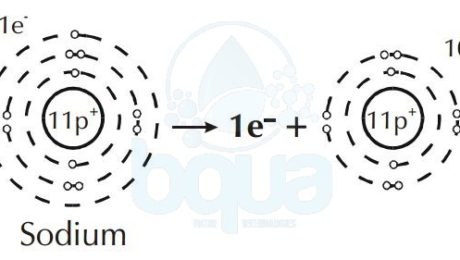
Furthermore, an element like Sodium will give up an electron to attain a full outer orbital. This results in a difference and unbalance between electrons and protons in the same atom.
When in an atom protons (+ve) are more than electrons (-ve) = result is positive ion (cation).
Sodium atom loses one electron become Sodium positive ion cation
Some atoms give up more than one electron to have a total outermost orbital. While other atoms will acquire more than one electron in order to fill the outer orbital. Since electrons have a negative charge (negative ion) and protons have a positive charge (positive ion), a difference in the number of electrons and protons results a net charge. This is when an atom is therefore called an ion.
Depending upon whether it gains or loses an electron, an ion will have either a positive or a negative
charge. Cations are ions with a net positive charged and anions are ions with a net negative charge. We know that opposite charges are attracted while same charges are repelled. That means that cations and anions are attracted to one another. The strength of the attraction may make ions form a solid called a crystal lattice.
- Published in Water Chemistry, Water Treatment
What is a molecule?
A molecule is a compound that was a substance formed by the chemical bonding of elements. Like an atom is the smallest particle of an element, the smallest discrete particle of a compound is a molecule.
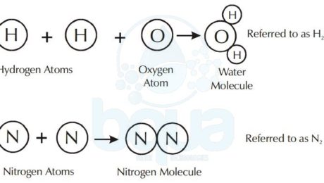
A molecule is made up of atoms from one or more elements. For example, the water molecule consists of two atoms of hydrogen chemically bonded to one oxygen atom. The nitrogen molecule consists of two nitrogen atoms bonded together.
Water Compound formed from Hydrogen Atoms and Oxygen Atoms
One mole equals 6.022×10^23 atoms (602,200,000,000,000,000,000,000 atoms). It is also called Avogadro Number or Avogadro Constant for the man credited for the number. Remember, one mole, or one atomic weight, or one molecular weight, or one Avogadro’s Number of any substance always contains 6.022×10^23 atoms, or molecules of that substance.
In the case of atoms, we describe the weight of one mole; the gram atomic weight. In the case of molecules, we describe it as the gram molecular weight.
Molecules are described by chemical formulas which use the chemical symbols found on the periodic table. Along with numbers to describe the number of atoms of that particular element found in the molecule.
Molecule Name Composition:
– CaSO4 – Gypsum, Calcium Sulfate – One atom of calcium, one sulfur, and four of oxygen.
– NaHCO3 – Baking Soda, Sodium Bicarbonate – One atom of sodium, one atom of hydrogen, one atom of carbon, and three atoms of oxygen.
– Al2(SO4)3 – Alum, Aluminum Sulfate – Two atoms of aluminum, three atoms of sulfur, and twelve oxygen.
– H2S – “Rotten Egg Gas”, Hydrogen Sulfide – Two hydrogens, and one atom of sulfur.
- Published in Water Chemistry, Water Treatment
What is Atomic Weight
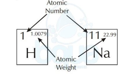
The atomic weight is simply the weight of one mole (6.022×10^23 atoms) of an element. The periodic table of elements shows the atomic weight on the upper right. The picture below shows an example of Hydrogen and Sodium atoms. Atomic weight of Hydrogen is 1.0079 when rounded to the nearest tenth = 1.0 gram. Same with Sodium atom, atomic weight is equal to 23.0 grams. For a molecule, to calculate the molecular weight we add the sum of atomic weights of the atoms in molecule.
atomic number and atomic weight in periodic table of elements
On the other hand, a gram atomic weight is the weight of one mole of an element, equal to its weight expressed in grams.
- Published in Water Chemistry, Water Treatment
What is a Functional Group
Molecular compounds owe their individual properties to functional group. These are combinations of atoms which may appear in various parts of the molecule. A list of major functional group listed below.
| Illustrative Example | Name of Functional Class | Functional Group |
| CH3CH2CH3 | Alkanes | C-C |
| CH3CH=CH2 | Alkenes | C=C |
| CH3CH/CH | Alkynes | C/C |
| CH3CH2CH2OH | Alcohols | C–OH |
| Aldehydes | ||
| Ketones | ||
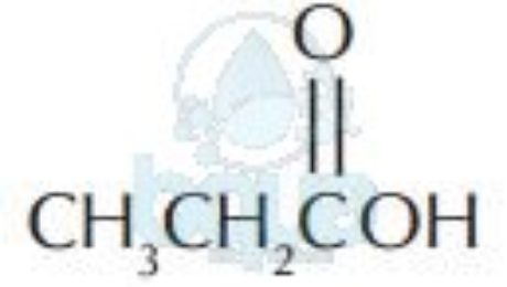
| Acids | ||
| CH3CH2CH2NH2 | Amines | C-NH2 |
| CH3OCH2CH3 | Ethers | -C-O-C- |
| CH3CH2CH2Br | Halides | C-Br |
The difference in electronegativity of two bonding atoms determines if the bond will be polar or nonpolar (read about polarity). The bond between two identical atoms is always nonpolar, (for example: C-C, C=C, C=C; H-H, O=O, etc…). Bonds between atoms with electronegativities which are nearly the same are nonpolar (for example C-H). Bonds between atoms with electronegativities which are significantly different (commonly 0.9) are polar (for example, C-O, H-O, C=O, and N-H).
One molecule, especially a large complex molecule, may have more than one type of functional group. One specific functional group may be repeated several times.
A functional group may alter the properties of a compound such as melting point, boiling point, solid structure, and solubility. A functional group on an organic molecule also contribute to its hydrophobic and hydrophilic properties. Surfaces composed of nonpolar molecules will be hydrophobic. Surfaces composed of compounds containing polar bonds will be hydrophilic. You can also read about surface tension.
- Published in Water Chemistry, Water Treatment
What is a mole definition
Atoms are very small. In order to find a unit to measure an atom; scientists decided to use a unit consisting of a large group of atoms while quantifying them. The unit used for atomic measurement is called a mole.
A particular number of atoms of each element is equal to a mole of this element. A unit of measurement of the weight of a mole of atoms is called the gram atomic weight of the element and it is expressed in grams. On the other hand, one mole of a specific molecule is a gram molecular weight of this molecule.
You can find the atomic weight number in the upper right hand corner of the element box on the periodic table of elements. It basically expresses the weight of one mole of this particular element in grams.
For example, one mole of the hydrogen atom weighs 1.0079 grams. Since numbers are generally rounded off to the nearest tenth of a gram, one mole of hydrogen atoms weighs 1.0 gram. While a weight of one mole of Carbon is 12.0 grams.
atomic measurement what is a mole definition avogadro number
Avogadro Number is one mole
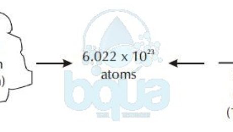
A mole is equal to 6.022×10^23 atoms (602,200,000,000,000,000,000,000 atoms). It is also called Avogadro Number for the man who first acknowledged the number.
One mole, or one atomic weight, or one molecular weight, or one Avogadro’s Number of any substance always contains 6.022 x 10^23 atoms, or molecules of that substance, not necessarily atoms.
- Published in Water Chemistry, Water Treatment

