


What is a mole definition
Atoms are very small. In order to find a unit to measure an atom; scientists decided to use a unit consisting of a large group of atoms while quantifying them. The unit used for atomic measurement is called a mole.
A particular number of atoms of each element is equal to a mole of this element. A unit of measurement of the weight of a mole of atoms is called the gram atomic weight of the element and it is expressed in grams. On the other hand, one mole of a specific molecule is a gram molecular weight of this molecule.
You can find the atomic weight number in the upper right hand corner of the element box on the periodic table of elements. It basically expresses the weight of one mole of this particular element in grams.
For example, one mole of the hydrogen atom weighs 1.0079 grams. Since numbers are generally rounded off to the nearest tenth of a gram, one mole of hydrogen atoms weighs 1.0 gram. While a weight of one mole of Carbon is 12.0 grams.

atomic measurement what is a mole definition avogadro number
Avogadro Number is one mole
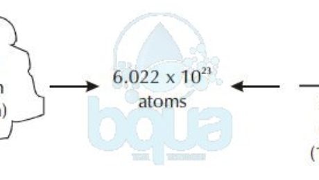
A mole is equal to 6.022×10^23 atoms (602,200,000,000,000,000,000,000 atoms). It is also called Avogadro Number for the man who first acknowledged the number.
One mole, or one atomic weight, or one molecular weight, or one Avogadro’s Number of any substance always contains 6.022 x 10^23 atoms, or molecules of that substance, not necessarily atoms.
Molecular Weight
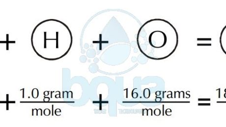
A molecular weight is simply the weight of one mole (6.022×10^23 molecules) of a compound. Like the gram atomic weight, in the case of molecules, we describe the weight of one mole (6.022 x 10^23 molecules) as the gram molecular weight. To calculate the gram molecular weight of a molecule, we add the gram atomic weight of each atom comprising the molecule. For example, to calculate the gram molecular weight of water (H2O), we would add the gram atomic weight of oxygen plus two times the gram atomic weight of hydrogen.
An example of H2O water molecule: The molecular weight is equal to the sum of atomic weights of Hydrogen and Oxygen atoms. Since there are two Hydrogen atoms and one Oxygen. Total is equal to 2(1.0 gram of Hydrogen) + 1(16.0 grams of Oxygen) = 2.0 + 16.0 = 18.0 grams molecular weight. It is also the weight of one mole of water.

Water Compound formed from Hydrogen Atoms and Oxygen Atoms

gram molecular weight of water molecule
Reverse Osmosis membranes will reject ions because of their charge. The membranes will also reject non-charged compounds (like organics) based upon molecular size. Generally, any organic less than 100 molecular weight will not be well rejected. Rejection of organics also depends upon the geometry of the molecule.
Molecular weight is important in organic chemistry since most organic molecules are quite large. Some polymers can have molecular weights in the millions.
What is Continuous Electrodeionization (CEDI)
The continuous electrodeionization is a recent invention that was brought by a water treatment company which patented the CEDI technology. CEDI which is the abbreviation for the continuous electrodeionzation is considered as a smart evolution to conventional Electrodialysis Reversal (EDR) technology. It is introduced as a blend of ion exchange membranes, ion exchange resins and electricity. The difference between the resins used in this technology and the conventional Ion Exchange resins made of divinyl benzene (DVB) is that these resins are continuously regenerated in the continous electrodeionzation without the need for regeneration chemicals or salt.
The way Continuous Electrodeionization CEDI works is so simple. It is actually very similar to Electrocoagulation in respect to the use of plates/electrodes (anode and cathode). Applying a DC current to plates, it turns them to anode and cathode. This is done in order to attract dissolved solids consisted of mainly anions (negatively charges ions) and cations (positively charged ions). The anode electrode will attract negatively charged ions while the cathode will attract positively charged ions. When ion exchange membranes made of cation selective resins are inserted right close to the cathode, it will block the passage of anions and water molecules. On the other hand, when we insert an ion exchange membrane made of anion selective resin close to the anode, it will block the passage of cations and water molecules and only allow anions to pass.
Continuous Electrodeionization Operation and Resin Regeneration
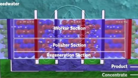
This configuration of membranes and electrodes form the framework of a Continuous Electrodeionization CEDI module. This process is however slowed down by the slow speed of which ions move in water, in fact the low conductivity of water molecules impedes ions removal. Meaning, as ions move outward, the water in the dilute chamber become purified. As ion levels decreases, electrical resistance increases and eventually the whole process slows down. That was solved by adding anions and cations selective resin beads between the two Ion Exchange membranes which reduces the electrical resistance.
The surface of the beads in the continuous electrodeionization CEDI module acts as an ion transport bridge. So that the ions can move quicker through the membranes at to the electrodes. Continuously adding resin beads – Ion Exchange selective membranes sandwiches, creates a series of water purification compartments where product and brine exit the system. As feed water is pumped into the system, it is diverted into separate compartments: concentrate and purification compartments. These two streams remain separated throughout the process because only ions can pass through the membranes. Ions migrate and accumulate in the concentrating compartment where they are washed away into the reject stream; exit the system as concentrate. The water leaving this compartment contain a concentration of ions of approximately 10 – 20x higher than the original feed water. This water can be either drained, recycled or reclaimed for further treatment.

Continuous Electrodeionization CEDI module
At the top of the purification compartment the ion concentration is at its highest. The surface of the resin beads act as a conductive path effectively moving the ions to the membranes. At the lower end of the purification, the ion concentration is reduced to the parts per trillion (ppt) level. The electric field becomes concentrated between the resin beads and the surrounding water resulting an electrochemical reaction. Where water splitting occurring into Hydrogen and Hydroxide ions which is essentially acid and caustic. The acid and caustic generated is what regenerated the resin beads by replacing other trace ions remaining. This exactly what happens in conventional IX deionization systems. A result is a chemical free operation where the electrical potential does all the work and extends the life of the resin.
What is a Pressure Membrane / Pressure-Driven Membrane
The pressure membrane processes are:
– Reverse osmosis (RO)
– Nanofiltration (NF)
– Ultrafiltration (UF)
– Microfiltration (MF)
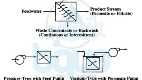
A pressure membrane is a membrane that functions by applying a pressure. A pressure membrane is permeable to water but not to substances which are rejected and removed. All membranes including any pressure-driven membrane separate feedwater into two streams: permeate and concentrate streams. The permeate (for RO, NF, or UF) or filtrate (for MF) stream passes through the membrane barrier. The concentrate (or retentate) stream contains the substances removed from the feedwater after the pressure membrane barrier rejects it.
Actually, the driving force for these pressure membrane processes may come from (1) a pressurized feedwater source with the membranes installed in pressure vessels, called modules. Or (2) a partial vacuum in the filtrate/permeate flow stream caused by use of a filtrate/permeate pump or gravity siphon. The vacuum-driven processes typically apply to MF and UF only and have membranes submerged or immersed in nonpressurized feedwater tanks.

pressure membrane process using feed or permeate pumps
Pressure membrane processes are designed for cross-flow or dead-end operating modes. In the cross-flow mode, the feed stream flows across the pressure membrane surface. And permeate (or filtrate) passes through the pressure-driven membrane tangential to the membrane surface. Moreover, cross-flow operation results in a continuously flowing waste stream. A cross-flow system design sometimes contain a concentrate recycle. Also with a reject stream (feed-and-bleed mode). Many MF and UF systems treating relatively low turbidity waters are also designed to operate in a dead-end flow pattern where the waste concentrate stream is produced by an intermittent backwash. The figure below shows the relative removal capabilities for pressure-driven membrane processes and compares these processes with media filtration.

pressure membrane processes RO NF UF MF difference pore size rejection
In fact, MF and UF separate substances from feedwater through a sieving action. Separation depends on the pressure membrane pore size and interaction with previously rejected material on the membrane surface. Furthermore, NF and RO separate solutes by diffusion through a thin, dense, permselective (or semi-permeable) membrane barrier layer, as well as by sieving action. The required pressure membrane feed pressure generally increases as removal capability increases.
