


What is Surface Tension
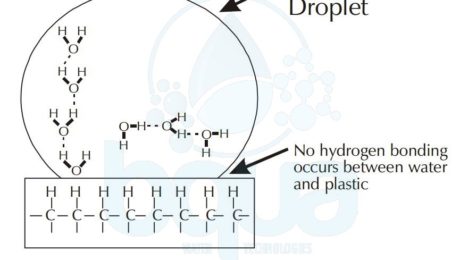
Surface tension is one of the properties of water that is created by the Hydrogen bond. Surface tension is the reason a water droplet can have different shapes on different surfaces. As we all noticed, when we fill a glass of water to the top, water level may actually be above the glass rim. The explanation for this occurrence is the high surface tension of water on a hydrophilic surface like glass due to hydrogen bond.

surface tension of water on plastic hydrophobic

surface tension of water droplet on hydrophilic glass
Hydrophobic and Hydrophilic Examples
On the other hand, a water droplet tends to form a sphere like shape on a hydrophobic surface like for example plastic. Therefore, a drop of water will tend to spread on a clean glass surface. To simply explain why this happens, we will analyse the phenomenon on a molecular level. In the example of plastic and since it is a nonpolar substance; water will tend form hydrogen bonds with itself. In the example of glass which is polar; water molecules will form hydrogen bonds with the silicon dioxide of the glass. And this is what makes water tend to spread on the glass surface; attraction to glass. Read more about polarity.
Another example explaining surface tension, using a small glass tube called a capillary tube. If we place the end tip of this tube in a glass of water, water will drawn. This is because of the hydrogen bond occurring between the SiO2 of the glass tube and the Oxygen atoms in the water molecules. The definition of hydrophilic which is what describes the glass in this situation means water loving. While definition for Hydrophobic which is plastic in the above example means water hating.

surface tension capillary tube example water glass hydrophilic
A unit of measurement for the surface tension of water is dynes/cm at room temperature. Which is the force you have to overcome in order to break the surface tension of a water droplet (1cm in length). The lower the temperature the less surface tension. Hot water makes a better cleaning solution since it is considered a better wetting agent. This is due to low surface tension of hot water which allows it to better react with detergents which are hydrocarbons with a polar end called a functional group.
Manganese and Iron in Water
Manganese and Iron in water have secondary MCLs (Maximum Contaminant Level) (SMCLs – Secondary Maximum Contaminant Level) of 0.05 and 0.3 mg/L, respectively. These SMCLs have been considered as safe limits to avoid the staining of plumbing fixtures and laundry, but experience shows that lower levels are desired to avoid difficulties. Targets of < 0.1 mg/L iron and < 0.02 mg/L manganese should be normal water quality goals.
Dissolved Manganese and Iron in water are normally in the reduced state (Fe II and Mn II) and can be removed by oxidizing to Fe III and Mn IV, where they will precipitate as Fe(OH)3 and Mn(OH)2. Precipitates are subsequently removed in sedimentation and/or filtration steps. Several oxidants are available for this process, namely, chlorine, chlorine dioxide, ozone, and potassium permanganate. They are also removed through conventional lime softening treatment. Most oxidants also react with organics in the water, so some testing is normally required to determine the appropriate dose.
Small well treatment water systems with excessive levels of iron and manganese often apply an oxidant, provide a period of detention for the reaction to take place, and then remove the precipitated Manganese and Iron in water with a pressure filter.
Cheapest way to remove iron from well water:
As discussed above, cheapest way to remove iron from well water is to use Chlorine as an effective oxidant for iron removal. Oxidation to Fe(OH)3 proceeds rapidly which is a Ferric Fe3+ Hydroxide (Iron III Hydroxide). Which is a precipitate of Red/Brown color that can be easily removed by a conventional cartridge filter (sedimentation/filtration). It is not as effective for manganese removal, however, at normal pH conditions. Chlorine is also used to maintain MnO2(s) coatings on filter media, which allows for the continuous removal of manganese through the filter bed.
Potassium permanganate, KMnO4, has often been used at treatment plants for oxidation of these two dissolved species. Potassium permanganate is best used at the front of the treatment works to allow contact prior to the introduction of other chemicals. The reactions have been found to be both pH- and temperature-dependent. Permanganate is also used for the regeneration of Manganese Green Sand filter media.

Green Sand Filter iron in water removal
Ozone has been used for Manganese and Iron removal from water because it is effectively used for iron and manganese oxidation. Often in conjunction with protection against tastes and odors. Iron is almost instantaneously oxidized by ozone while manganese is somewhat slower, but even this reaction is normally complete within about 30 seconds.
Oxidation using chlorine dioxide is generally complete within a few seconds. Chlorine dioxide is also normally applied at the head of the treatment process. It has the advantage over chlorine of not forming chlorinated DBPs (Disinfection by-products), but a regulated DBP, chlorite, is one of its by-products. Depending on the concentrations of Manganese and Iron in water, the chlorite formed may limit the use of chlorine dioxide for this application unless the chlorite is subsequently removed by another process.
Lime softening is also an effective way for Manganese and Iron removal. Again, the reduced forms are oxidized to insoluble precipitates, and they are removed along with the lime sludge. The chemical reaction that describes this oxidation process is as follows:
4Fe(HCO3)2 + 4Ca(OH)2 + 2H20 + O2 –> 4Ca(HCO3)2 + 4Fe(OH)3
What is Forward Osmosis
Fundamentally, Forward Osmosis exploits a naturally occurring phenomenon (Osmosis). Which is simply the water transport over a semi-permeable membrane from a low concentration to a high concentration. In a perfect world, the semi-permeable membrane permits water to pass through it however rejects all salts and undesirable components. The high salinity solution acts as the draw solution, which has a higher concentration than the feed water. To initiate the passage and attract water to pass through the membrane from the feed side to itself. In this manner, Forward Osmosis requires less energy (applied pressure) to transport a water stream through the membrane. In comparison to the pressure driven membrane procedures, for example, reverse osmosis (RO). However, as opposed to Reverse Osmosis, the result of Forward Osmosis is not fresh water but rather a diluted draw solution. It is a blend of the feed water and draw solution. In this way, a following filtration or separation process must be performed to extract clean water and to recover the draw solution. The draw solution consists of either a single or multiple simple salts or can be a substance specifically tailored for forward osmosis applications.
The following step of filtration might be energy intensive relying upon the draw solution and the recycling procedure. Hence, for potable water production, one must consider the energy utilization of both the Forward Osmosis procedure and the DS recovery. So that we can eventually make a reasonable examination and run comps between Forward Osmosis and other water treatment advancements. Or else, the conclusion could be one-sided and deceiving. In any case, Forward Osmosis might be more practical than pressure driven membrane technologies for water reuse. Only if the recovery of the Draw Solution is not required. Consequently, Researches and developments made on Forward Osmosis will be used to organize those procedures and applications without reusing the Draw Solution.
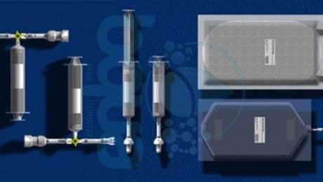
One of the most significant applications for Forward Osmosis is done by NASA. Six forward osmosis kits will fly aboard space shuttle Atlantis on the STS-135 mission by NASA. Scientists from NASA’s Kennedy Space Center in Florida plan to test a space adapted version of a Forward Osmosis bag. This will happen aboard space shuttle Atlantis during the STS-135 mission summer 2017. The group at Kennedy, led by NASA Project Manager Spencer Woodward, will include in the shuttle’s cargo six forward osmosis bag kits for the astronauts to test. The bags’ manufacturer, made a few adaptations to their commercial product for spaceflight. The idea is to make a fortified drink that provides hydration and nutrients from all sources available aboard a spacecraft, such as wastewater and even urine.

Forward Osmosis bag kit NASA experiment
Up until today, Forward Osmosis still experiences issues as a cost-effective innovation for direct seawater desalination. As a result of its high energy utilization and absence of efficient DS with -close to – negligible reverse flux. Regardless of many innovative advances in DS recently made, challenges still exist to: First, limit the reverse flux of DS. Secondly, mitigate internal concentration polarization (ICP) and Lastly, find better and easier recovery strategies. In conclusion, Forward Osmosis represents a forthcoming technology with a very low impact on the environment.
What is Electrodialysis ED
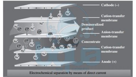
In electrodialysis (ED)–based desalination systems, the separation of minerals and product water is achieved through the application of direct electric current to the source water. This current drives the mineral ions and other ions with strong electric charge that are contained in the source water through ion-selective membranes to a pair of electrodes
of opposite charges. As ions accumulate on the surface of the electrodes, they cause fouling over time and have to be cleaned frequently in order to maintain a steady-state Electrodialysis ED process. A practical solution to this  challenge is to reverse the polarity of the oppositely charged electrodes periodically (typically two to four times per hour) in order to avoid frequent electrode cleaning.
An Electrodialysis ED process that includes periodic change of the polarity of the system’s electrodes is referred to as an electrodialysis reversal EDR process. At present, practically all commercially available ED systems are of the EDR type. Electrodialysis ED systems consist of a large number (300 to 600 pairs) of cation and anion exchange membranes separated by dilute flow dividers (spacers) to keep them from sticking together and to convey the desalinated flow through and out of the membranes. Each pair of membranes is separated from the adjacent pairs above and below it by concentrate spacers which collect, convey, and evacuate the salt ions retained between the adjacent membranes. The membranes used for ED are different from those applied for Reverse Osmosis RO desalination—they have a porous structure similar to that of microfiltration and ultrafiltration membranes. Reverse Osmosis membranes do not have physical pores. Electrodialysis ED membranes are more resistant to chlorine and fouling and are significantly thicker than RO membranes.

electrodialysis ED membrane desalination technology schematic process system
It is important to note that a single set of EDR stacks can only remove approximately 50 percent of salts. As a result, multiple EDR stacks connected in series are often used to meet more stringent product water Total Dissolved Solids TDS targets. It should be pointed out that compared to brackish water RO membranes, which typically yield only up to 85 to 90 percent recovery, Electrodialysis Reversal EDR systems can reach freshwater recovery of 95 percent or more. The energy needed for ED desalination is proportional to the amount of salt removed from the source water. TDS concentration and source water quality determine to a great extent which of the two membrane separation technologies (RO or ED) is more suitable and cost effective for a given application. Typically, ED membrane separation is found to be cost competitive for source waters with TDS concentrations lower than 3000 mg/L. This applicability threshold, however, is a function of the unit cost of electricity and may vary from project to project.
The TDS removal efficiency of Electrodialysis ED desalination systems is not affected by non-ionized compounds or objects with a weak ion charge (i.e., solids particles, organics, and microorganisms). Therefore, ED membrane desalination processes can treat source waters of higher turbidity and biofouling and scaling potential than can RO systems. However, the TDS removal efficiency of ED systems is typically lower than that of Reverse Osmosis systems (15.0 to 90.0 percent versus 99.0 to 99.8 percent), which is one of the key reasons why they have found practical use mainly for brackish water desalination. In general, Electrodialysis Reversal EDR systems can only effectively remove particles that have a strong electric charge, such as mono- and bivalent salt ions, silica, nitrates, and radium. EDR systems have a very low removal efficiency with regard to low-charged compounds and particles—i.e., organics and pathogens. Table below provides a comparison of the removal efficiencies of distillation, ED, and RO systems for key source water quality compounds.
| Contaminant | Distillation (%) | ED/EDR (%) | RO (%) |
| TDS | >99.9 | 50-90 | 90-99.5 |
| Pesticides, Organics/VOCs | 50-90 | <5 | 5-50 |
| Pathogens | >99 | <5 | >99.99 |
| TOC | >95 | <20 | 95-98 |
| Radiological | >99 | 50-90 | 90-99 |
| Nitrate | >99 | 60-69 | 90-94 |
| Calcium | >99 | 45-50 | 95-97 |
| Magnesium | >99 | 55-62 | 95-97 |
| Bicarbonate | >99 | 45-57 | 95-97 |
| Potassium | >99 | 55-58 | 90-92 |
One important observation from this table is that, as compared to distillation and RO separation, ED desalination only partially removes nutrients from the source water. This fact explains why EDR is often considered more attractive than RO or thermal desalination (which remove practically all minerals from the source water) if the planned use of the desalinated water is for agricultural purposes—i.e., generating fresh or reclaimed water for irrigation of agricultural crops.
Construction and equipment costs for brackish water reverse osmosis (BWRO) and EDR systems of the same freshwater production capacity are usually comparable, or EDR is less costly, depending on the Reverse Osmosis membrane fouling capacity of the source water. However, since the amount of electricity consumed by EDR systems is directly proportional to the source water’s salinity, at salinities of 2000 to 3000 mg/L the energy use of EDR systems usually exceeds that of BWRO or nanofiltration systems for source waters. Therefore, EDR systems are not as commonly used as RO systems for BWRO desalination and are never applied for seawater reverse osmosis (SWRO) desalination.
It should be pointed out, however, that salinity is not the only criterion for evaluating the cost competitiveness of EDR and BWRO systems. Often, other compounds such as silica play a key role in the decision making process. For example, at the largest operational EDR plant worldwide at present—the 200,000 m3/day Barcelona desalination facility in Spain—this technology was preferred to BWRO desalination because the brackish surface water source for this plant—the Llobregat River—contains very high level of silica, which would limit recovery from a BWRO plant to only 65 percent; the EDR system can achieve 90 percent recovery. In addition, the Llobregat River was found to have very high organic content, which was projected to cause heavy fouling and operational constraints on a BWRO plant of similar size.
Reference: “Desalination Engineering” by Nikolay Voutchkov
