


What is Diatomaceous Earth DE Filter
Diatomaceous Earth DE filtration – DE Filter –  has been used effectively for drinking water treatment since 1942. Diatomaceous Earth DE Filter was adopted as a standard method for the U.S. Army. The DE filter was selected because of its portability and effectiveness in removing Entamoeba histolytica cysts (Black and Spaulding, 1944). These cysts are pervasive in some parts of the world and are difficult to control with disinfectants alone. The capability of DE filter to effectively remove particulates applies equally well to the latter concerns of Cryptosporidium and Giardia. Where cyst removals of approximately 6 logs have been achieved (Ongerth and Hutton, 1997). DE filter is commonly called a pre-coat filter because of the pre-coat of filter leaves that initiates every operating cycle.
Although DE filter has DE as the most common pre-coat material used, other pre-coat material such as ground perlite performs as well in many applications. For many years, the type of equipment available limited the use of a Diatomaceous Earth DE filter for municipal drinking water treatment. The use of stainless steel and plastics in the fabrication of equipment has significantly changed the performance capability of the filters by improving their ease of operations and maintenance. DE Filter named upon Diatomceous Earth which is mined from the fossilized remains of microscopic plants called diatoms, deposited in what were the beds of ancient oceans. A powdered medium is manufactured from the diatomite deposits that is almost pure silica. One of the more common diatomite media used for drinking water treatment has a mean particle size of 22.3/xm with 80% of the particles ranging in size from 5 to 64 p~m. This medium, when deposited on the filter septum, has an average pore size of about 7.0/xm.
Diatomaceous Earth Filter Operation
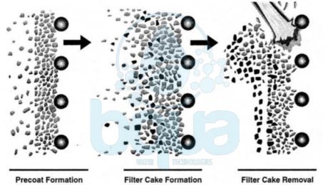
As illustrated below, Diatomaceous Earth DE filter operations occur in three steps:
1. A precoat of about % in. (3 mm) is deposited on the filter.
2. After the precoat has been deposited, filtering begins. And at the same time a small amount of Diatomaceous Eearth material (called body feed) is added to the source water. This is to maintain the porosity of the media.
3. Particulates in the source water are trapped in the pre-coat layer until it reaches maximum head loss. At which time the filter run is terminated and media material is cleaned from the septa.

diatomaceous earth DE filter operation design
Porosity Control of DE Filter
The principal requirement for maintaining effective Diatomaceous Earth DE filter runs is to maintain the porosity of the filter cake. Source water solids generally vary in size and are mixture of relatively inert matter and solids that are predominantly organic. If source water is filtered through the pre-coat alone, the buildup of solids and compression of the accumulated cake quickly reduces DE filter cake porosity. And head loss increases at an exponential rate. This may be avoided by adding body feed to the source water in sufficient amounts to produce a constant flow versus head loss relationship. Although the rate of flow does not affect effluent quality or turbidity breakthrough, the flow rate for pre-coat filters should generally be limited to about 2 gpm/ft 2 (7.8 m/h). The shape of the pre-coat filter head loss curve that reflects both feed and flow conditions is. Therefore, an important feature to control effective filter run performance.
Supplementary Treatment for Diatomaceous Earth DE Filter
Supplementary measures are added to the basic DE filter process to enhance the filtration process and to expand the process to remove some non-particulate constituents. Natural color in source water supplies is caused by either organic or mineral matter. Color results from the decay of plant matter or from the solubilization of iron in the soil. And in many instances the mineral and organic matter are bound together. Therefore color is present either in particulate form or in solution. Particulate color consists mostly of negatively charged colloids, and even though the pre-coat medium has low pore size, charged colloids pass through unless the charge is neutralized.
The use of a strong oxidant such as ozone has been demonstrated to be effective in conditioning color for removal. When color is particulate rather than dissolved, DE filters reduce source water color of about 25 color units (CU) and less to below 5.0 CU. With source color between 25 and 60 CU, filter effluent is generally no higher than 10 CU. Supplemental treatment such as pre-ozonation or alum-coated media may be required. They can improve removal of particulate color and to reduce dissolved color. Dissolved iron precipitates by aeration or by adding a strong oxidant so that the iron is removed as a particulate in DE filtration. The use of magnesite (magnesium oxide) is found to facilitate removal of some forms of iron. Magnesite mixed along with body feed is held for about 10 rain to form negatively charged suspension of magnesium oxide. MgO gradually undergoes hydration and solution.
Manganese may be removed with DE filer with potassium permanganate (KMnO4) added to the body feed. Followed by flow detention, usually from 10 to 20 min. Detention time is important and should be determined in bench and pilot tests. The rate of KMnO4 addition and body feed rate depend on the amount of manganese in the source water. And on also other water quality characteristics. Where iron and manganese are both present in source water, supplementary conditioning must usually be accomplished in separate steps. With iron treatment preceding the KMnO4 addition. When there is a large amount of iron to be removed, it may be necessary to have two filters in series. With iron conditioning preceding the first filter and the addition of KMnO4 and detention between the first and second filters.
Practically the only carryover of solids in DE filter effluents would be very fine Diatomaceous Eearth particles used in pre-coat and body feed. Although the presence of these particles is innocuous to health, effluent water turbidity must meet the established requirements. Use of a finer Diatomaceous Eearth for pre-coat can sometimes achieve lower turbidity levels. A slight reduction in the applied flow rate can also help to improve effluent turbidity. Where only slight additional turbidity reduction is needed. The use of a simple cartridge filter following the DE filter accomplishes the desired DE removal. Use of cartridge filters to polish the effluent will be more effective for the lower-capacity DE installations when solids carryover is minimal. Note that without the addition of separate, additional treatment processes, DE filtration will not reduce the organic content of source water.
You can learn more about the Diatomaceous Earth DE Filter Design
Reference: Water Treatment Plant Design
What is Diatomaceous Earth DE Filter Design
Several options are available in designing each of the flat-leaf DE filter elements, as well as in the integrated assembly DE filter design.

diatomaceous earth DE filter design flat leaf element
Types of DE Filter
Two basic groups of DE filter are available. If source water is to be forced through the filter under pressure, the containment vessel must be closed. DE filter operates under a vacuum, on the other hand, may be open vessels. Although there is theoretically no limitation to what pressure may be applied to a pressure-type filter. Practical considerations of pumping costs have limited head loss to a maximum of 35 psi (241 kPa). Most systems used for drinking water filtration are designed for a maximum head loss of 25 psi (172 kPa).
DE Filter Design Construction
Pressure filters are always constructed as cylindrical pressure vessels mounted either vertically or horizontally. Most units fabricated today are made of stainless steel for the shell and most internal parts. The type of stainless steel used depends on the corrosivity of the water being treated. Vacuum filters are built as rectangular tanks. Because of the low differential heads they are subject to, vacuum filter containments and internal parts, except certain structural supports, are most often fabricated of plastics for their chemical resistance and reduced maintenance. For larger units, the containment vessel may be constructed of concrete.
DE Filter Elements
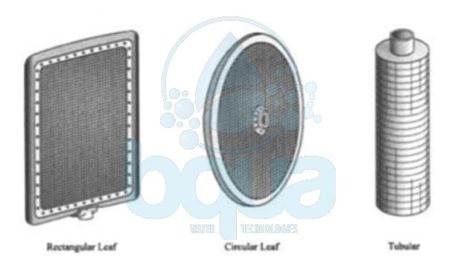
Inlet water flow is introduced to a DE filter through the containment wall, fitted with an internal baffling device to prevent disturbance of the filter cake. Filter cake may be cleaned from the filter by scraping, vibration, hydraulic bumping (surging), or manually hosing down the septa from the top of an open vessel. Many arrangements of filter elements are available, constructed in both a tubular and flat form, with the flat (or “leaf’) design being by far the most common.
DE Filter elements may be mounted either horizontally or vertically, and they may be either fixed in position or able to rotate. Vertical mounting of the leaves is used almost exclusively for water treatment applications. Most pressure and vacuum filters constructed today have fixed leaves mounted by means of spigot-type “push-on” outlets installed in sockets on a manifold and sealed by O rings or flat gaskets. The outlet manifold is usually located below the leaves to provide them with support while allowing gravity to assist in seating the push-on connections.
Variations for both leaf connections and manifold location are selected depending on operating conditions and requirements for inspection and maintenance. Fixed-leaf pressure filters may also be divided into retracting shell and retracting bundle types for internal access. Both options may be used for any size filter, but the retracting bundle type is is generally preferred for larger units. The retracting shell or tank design has the shell mounted on wheels on rails. An electric motor or hydraulic piston opens and closes the unit.
In the retracting bundle design, the shell head is suspended from an overhead monorail. The bundle, attached by the manifold and frame to the head, is retracted by means of the monorail, which is usually motor-driven. Internal rails attached to the shell support the end of the leaf bundles when the shell is opened. Thorough cleaning of the septa at the end of a filter run is important in maintaining peak efficiency. Most units used for water treatment sluice the cake with water sprays, which creates a slurry that can be easily handled and treated and does not require opening the filter vessel.
Fixed-leaf filters are usually cleaned with high-pressure spray jets mounted on oscillating spray heads, with single or multiple jets directed between the filter leaves. Rotating filter leaves usually have a stationary spray header, and coverage is obtained as the leaves rotate past the sprays. Open filters may be cleaned manually using high pressure sprays and may require covers over the units to contain the spray. Additional devices that may assist in the complete removal of the cake slurry from the filter containment include spray jets in the invert of the vessel or an air scour to suspend the material before the vessel is drained.

diatomaceous earth DE filter design rectangular circular tubular element
Leaf DE Filter Design
The flat DE filter leaf with a broad surface and limited thickness should be designed with the following goals:
• Leaf and outer frame must be stiff enough to resist warping under the force exerted at maximum differential pressure.
• The unit must have a backing screen to prevent the cloth septum from flexing under gradually increasing pressure.
• The path provided for filtrate flow must not restrict flow and must create minimal head loss through the leaf. It is essential that the filter cake remain undisturbed.
An adequate filter leaf design prevents the possibility of cake movement due to warping of the frame or flexing of the septum.
Central Drainage Chamber
There are three basic types of filter leaf drainage chambers. Heavy wire mesh with wire spacing up to 1 in. (2.5 cm); expanded metal sheets that provide a deeper chamber with increased rigidity. And the Trislot, a proprietary design having thin metal bars with welded transverse round or wedge-shaped wires.
DE Filter Backing Screen
The backing screen is an intermediate screen used when the irregular surface of the central drainage chamber may permit flexing of the cloth septa under conditions of varying pressure.
DE Filter Septum
Filter septum materials are cloth weaves made with either stainless steel wires or plastic monofilaments. The principal purpose of the septum is to retain the pre-coat, which must bridge the openings in the weave. Because openings in the weave are larger than the major portion of particulates in pre-coat material, the pre-coat is retained by bridging. The cloth septum must be uniformly woven to produce an even pre-coat that reduces the extent of the recirculation required to deposit the material. The weave must also be designed so that it sluices cleanly, drops the cake freely, and resists plugging and damage. One of the more common wire cloths for water filtration is a standard 24 × 110 Dutch weave. Another type of weave is the multibraid, composed of bundles of wire in both directions. This weave is less vulnerable to the entrapment of particles and blinding than the standard weave. Woven wire cloth may also be “calendered,” which involves passing the cloth through compression rollers to flatten the rounded wire at the surface of the weave. Calendering improves pre-coat retention characteristics and generally strengthens the cloth against rough treatment. Plastic cloth is used predominantly for vacuum-type DE filters and is available in a variety of weaves using either polyester or polypropylene monofilament. Plastic cloth may be supplied as a bag to envelop a filter leaf or as a cloth caulked into a leaf frame.
Binding Frame Closures
The binding frame surrounds the filter leaf to prevent leakage around the septum. The outside frame is also the principal structural element to provide rigidity and prevent warping. Depending on the shape, the outside binder may also collect flow from the central chamber and supplement flow routing to the outlet nozzle.
Vacuum Filter Leaves
Vacuum filter leaves used for drinking water treatment are often made of plastic. The central drainage chamber and outlet spigot are molded in a single piece, usually of high-impact styrene. Ridges or other raised patterns provide the required flow path. The raised pattern is spaced so that intermediate screens are not required. The septum, in the form of an envelope with zipperlike closures, is sealed at the bottom outlet by a gasket that also provides tight closure for the manifold connection.
Outlet Connections
Fixed-leaf filter leaves usually have spigot-type outlet connections made of castings machined to fit into the sockets of the outlet manifold. The central drain hub is used for rotating leaves and is of two-piece construction, clamped to the center of the circular leaf by bolts. The leaf outlet connection must be of sufficient size to allow full flow of the filtrate collected by the leaf at a minimum head loss. As leaf size and loading increase, the distribution of flow within the leaf and the transition to the outlet connection increase in importance.
Reference: Water Treatment Plant Design
What is Osmotic Pressure
Osmotic pressure is a function of dissolved substances. As in Osmosis, water will pass through a semi-permeable membrane from the lower concentration compartment into the higher concentration compartment. Osmotic pressure is simply what makes osmosis process occurs. The force of this flow is measured by measuring how much pressure must be applied to the higher salt concentration side in order to stop osmosis. This pressure then must be the force of osmosis. This pressure is called osmotic pressure. Osmotic pressure is a function of the number of collisions of water molecules with either side of the membrane. The more dissolved substances, of any kind, there are, the fewer the water collisions.
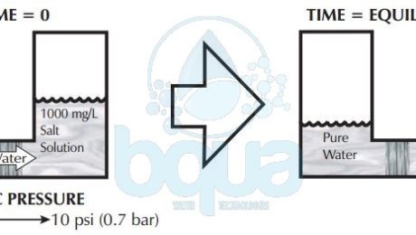
A very rough rule of thumb is that for every 100 mg/L or ppm of TDS (Total Dissolved Solids) the osmotic pressure is roughly 1 psi (0.07 bar). If pure water is separated from a 1000 mg/L TDS solution by a semi-permeable membrane. It will take around 10 psi of pressure on the 1000 mg/L side in order to stop osmosis. Therefore, the osmotic pressure forcing water from the pure water side into the 1000 mg/L side is 10 psi. While the greater water collisions are from the pure water side of the membrane, the reason for water movement left to right is due to the higher salt concentration on the right hand side.Â

osmotic pressure is what makes osmosis process occurs
Amount of osmotic pressure generated, therefore, is directly proportional to the amount of total dissolved solids (TDS) in the solution. Since every 100 mg/L creates around 1 psi (0.07 bar) of osmotic pressure, we simply have to divide the TDS by 100 (move the decimal to the left two places) in order to calculate the approximate pressure.
Now what happens when we have salt solutions on both sides of a semi-permeable membrane? Net osmotic pressure becomes important. The net pressure is the difference between the pressure of each of the solutions separated by a semi-permeable membrane. If two 1000 mg/L salt solutions separated by semi-permeable membrane, roughly 10 psi of osmotic pressure is being exerted by each solution. In this case the pressures are equal and opposite in direction. Substracting one from the other, the net osmotic pressure is zero. This is when the osmosis process reaches equilibrium.
Ultra-Permeable Membranes (UPM) – Desalination Technology
Recent studies introduce the promise of developing new membrane materials. These materials can desalinate water while showing far greater permeability than traditional reverse osmosis (RO) membranes. But the question remains whether higher permeability means significant reductions in the cost of desalinated water. A research evaluates the potential of ultra-permeable membranes (UPM) to improve the performance and cost of Reverse Osmosis.
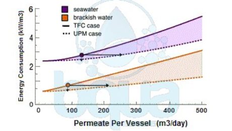
By modeling the mass transport inside a Reverse Osmosis pressure vessel (PV), the study assesses how much tripling water permeability lowers energy consumption. And also lowers the number of required pressure vessels for a particular desalination plant. The findings were very interesting, it proved that a tripling (3x) in permeability permits 44% fewer pressure vessels and 15% less energy for a seawater Reverse Osmosis plant (SWRO). This is done at a both given capacity and recovery ratio. Moreover, tripling permeability results in 63% fewer pressure vessels or 46% less energy for brackish water Reverse Osmosis (BWRO). However, it also shows that the energy savings of Ultra-Permeable Membranes (UPM) exhibits a law of diminishing returns due to thermodynamics and concentration polarization at the membrane surface.
Ultra-Permeable Membranes and Desalination Energy Consumption
The research shows that the development of ultra-permeable membranes helps reducing the energy consumption. It also reduces the number of pressure vessels required for Reverse Osmosis desalination. However, in terms of reducing energy consumption, the benefits of Ultra-Permeable Membranes (UPM) are limited to approximately 15% in the case of SWRO. It also shows that membranes with 3x higher permeability reduces number of pressure vessels by 44% for seawater reverse osmosis RO plants SWRO. And 63% in brackish water RO plants BWRO. This does not affect the energy consumption or permeate recovery.

ultra permeable membranes UPM thin film composite TFC for BWRO and SWRO
In case of energy consumption, ultra-permeable membranes proved to lower energy consumption of Seawater Reverse Osmosis systems – SWRO – by %15. While on the other hand lowered energy consumption of Brackish Water Reverse Osmosis systems – BWRO – by 46%. The research was made at the same permeate flow per pressure vessel as what is typical nowadays.
For greater permeability, the incremental energy savings are negligible but capital requirements continue to decrease. The reason behind it is using fewer pressure vessels. Despite concerns expressed in the research, it shows that concentration polarization does not neglect the benefits of Ultra-Permeable Membranes (UPM). Although it mitigates the benefits relative to what is expected in the absence of concentration polarization. As membrane permeability increases, also typical cross-flow velocities and mass transfer coefficients decrease. Permeate water flux increases routinely with membrane permeability. In spite of the fact that more advanced system designs are required to fully take advantage of greatly increased feed flow rates. Results suggest that advances in membrane science will continue to make desalination highly competitive as a fresh water supply in the near and far future.
