


Water Treatment Abbreviations and Acronyms – Glossary
This page includes a list of water treatment abbreviations and acronyms. It is considered as a small water glossary. Please feel free to contact us if you want to add a missing abbreviation.
| A | Water permeability coefficient |
| Ã… | Angstrom |
| ac | Acre |
| AOC | Assimilable organic carbon |
| AC | Alternating current |
| AC | Acticated Carbon |
| ADI | Acceptable daily intake |
| AO | Assimilable Organic |
| AWA | Australian Water Association |
| AWWA | American Water Works Association |
| B | Beta (concentration polarization factor) |
| B | Boron |
| Ba | Barium |
| BF | Bioflocculation |
| BF | Bag Filter |
| BOD | Biological oxygen demand |
| BOOT | Build-own-operate-transfer |
| Br | Bromide |
| BWRO | Brackish water reverse osmosis |
| °C | Degree Celsius (unit of temperature) |
| ΔC | Concentration gradient |
| Cf | Contingency factor |
| Ca | Calcium |
| CA | Cellulose acetate |
| CAPEX | Capital Expenditure investment |
| CaCO3 | Calcium carbonate |
| CCPP | Calcium carbonate precipitation potential |
| CCTV | Closed Circuit Television |
| CEDI | Continuous Electrodeionization |
| CF | Concentration factor |
| CF | Cartridge Filter |
| CFD | Computational fluid dynamics |
| cfu | Colony Forming Unit |
| CIP | Clean-in-place |
| cm | Centimeter |
| CMF | Conventional media filtration |
| CO2 | Carbon dioxide |
| COD | Chemical Oxygen Demand |
| CWA | Clean Water Act |
| DAF | Dissolved air flotation |
| DBB | Design-bid-build |
| DBO | Design-build-operate |
| DBP | Disinfection byproduct |
| DC | Direct current |
| DO | Dissolved oxygen |
| DOC | Dissolved organic carbon |
| DW | Dry weight |
| EC | Electrical conductivity |
| ED | Electrodialysis |
| EDR | Electrodialysis reversal |
| EPA | Environmental Protection Agency |
| EPC | Engineering, procurement, and construction |
| ERD | Energy Recovery Device |
| °F | Degree Fahrenheit (unit of temperature) |
| Fp | Feed pressure |
| FAO | Food and Agriculture Organization (United Nations) |
| FRP | Fiberglass-reinforced plastic |
| ft | Foot |
| ft2 | Square foot |
| ft3 | Cubic foot |
| FO | Forward Osmosis |
| Gpm | Gallons per minute |
| gal/min | Gallons per minute |
| gfd | Gallons per square foot per day |
| GAC | Granular Activated Carbon |
| GOR | Gained output ratio |
| GRP | Glass-reinforced plastic |
| GWA | Government of Western Australia |
| GWI | Global Water Intelligence |
| Hr | Hour |
| ha | Hectare |
| HACCP | Hazard Analysis and Critical Control Point |
| HBMP | Hydrobiological monitoring program |
| HC | Hydrocarbon (H-C bond) |
| HDPE | High-density polyethylene |
| HOCl | Hypochlorous Acid |
| Hp | Horsepower (unit of power) |
| H2S | Hydrogen sulfide |
| IDA | International Desalination Association |
| IPP | Industrial pretreatment program |
| IWA | International Water Association |
| IWW | Industrial Wastewater |
| IX | Ion exchange |
| J | Membrane permeate flux |
| JTU | Jackson Turbidity Unit |
| Kg | Kilogram |
| Km | Kilometer |
| kW | Kilowatt (unit of power) |
| kWh | Kilowatt-hour (unit of energy) |
| kWh/m3 | Kilowatt-hours per cubic meter (unit of energy) |
| L | Liter |
| LDPE | Low Density Polyethylene |
| LPM | Liter per Minute |
| lb | Pound |
| lb/in2 | Pounds per square inch (unit of pressure) |
| Lmh | Liters per square meter per hour |
| LSI | Langelier Saturation Index |
| LT2ESWTR | Long Term 2 Enhanced Surface Water Treatment Rule |
| M | Meter |
| m2 | Square meter |
| M3 | Cubic meter |
| M3/day | Cubic meters per day |
| MBF | Mixed-media Bed Filter |
| MBR | Membrane Bioreactor |
| MED | Multi-effect distillation |
| MED-TC | Multi-effect distillation with thermal compression |
| MENA | Middle East and North Africa |
| Meq | Milliequivalent |
| MF | Microfiltration |
| Mg | Magnesium |
| mg/l | Milligrams per liter |
| MGD | Million gallons per day |
| Mi | Mile |
| Min | Minute |
| ml | Milliliter |
| mm | Millimeter |
| Mn | Manganese |
| MSD | Multistage flash distillation |
| MTBE | Methyl tertiary butyl ether (gasoline additive) |
| mV | Millivolt |
| MVC | Mechanical vacuum compression |
| µg/L | Micrograms per liter |
| µm | Micrometer |
| µS/cm | Microsiemens per centimeter (unit of specific conductance) |
| Na | Sodium |
| NaOCl | Sodium Hypochlorite |
| NDMA | N-nitrosodimethylamine |
| NDP | Net driving pressure |
| NF | Nanofiltration |
| NOM | Natural organic matter |
| NP | Nanoparticle |
| NPDES | National Pollutant Discharge Elimination System |
| NTU | Nephelometric turbidity unit |
| O&M | Operations and maintenance |
| Opfc | Osmotic pressure on the concentrate side of the membrane |
| OCSD | Orange County Sanitation District |
| ORP | Oxidation-reduction potential |
| P | Phosphorus |
| Pr | Permeate recovery rate |
| PA | Polyamide |
| PDFB | Percent difference from balance |
| pH | Indication of the acidity or basicity of solution |
| PP | Polypropylene |
| ppb | Parts per billion (1 ppb = 1 µg/L) |
| ppm | Parts per million (1 ppm = 1 mg/L) |
| Ppt | Parts per trillion |
| PSI | Pound per square inch (unit of pressure) |
| PREN | Pitting resistance equivalent number |
| psu | Practical salinity unit (1 psu = 1000 mg/L) |
| PS | Polystyrene |
| PVC | Polyvinyl chloride |
| Qf | Fresh water flow |
| Rp | Permeate recovery rate |
| RBF | Rapid Bioflocculation Filter |
| RCRA | Resource Conservation and Recovery Act |
| RIB | Rapid infiltration basin |
| RO | Reverse osmosis |
| ROWPU | Reverse Osmosis Water Purification Unit |
| RSF | Rapid Sand Filtration |
| RWQCB | Regional water quality control board |
| s | Second |
| S | Membrane area of an element |
| Sp | Salt passage |
| Sr | Salt rejection |
| S. AZ | Southern Arizona |
| S. CA | Southern California |
| SAR | Sodium adsorption ratio |
| SARI | Santa Ana River Interceptor |
| SBR | Sequencing Batch Reactor (wastewater) |
| SCADA | Supervisory Control and Data Acquisition |
| SDI | Silt Density Index |
| SDWA | Safe Drinking Water Act |
| SDSI | Stiff–Davis Saturation Index |
| SER | Standard evaporation rate |
| SF | Sand Filter |
| SI | International System of Units |
| SRB | Sulfide Reducing Bacteria |
| SMBS | Sodium Metabisulfite |
| STE | Salinity tolerance evaluation |
| SUVA | Specific UV absorbance |
| SWRO | Seawater reverse osmosis |
| TCLP | Toxicity characteristic leaching procedure |
| TDS | Total dissolved solids |
| TFN | Thin-film nanocomposite |
| THC | Total hydrocarbons |
| TMP | Transmembrane pressure |
| TN | Total nitrogen |
| TOC | Total organic carbon |
| TP | Total phosphorus |
| TSS | Total suspended solids |
| u | Atomic mass unit |
| UF | Ultrafiltration |
| UIC | Underground Injection Control |
| US | United States (of America) |
| USBR | U.S. Bureau of Reclamation |
| USDW | Underground source of drinking water |
| UV | Ultraviolet radiation |
| VC | Vapor Compression |
| W. TX | Western Texas |
| WEF | Water Environment Federation |
| WET | Whole effluent toxicity |
| WHO | World Health Organization |
| WPA | Water purchase agreement |
| WQA | Water Quality Association |
| WTP | Water treatment plant |
| WWTP | Wastewater treatment plant |
| Y | Plant recovery |
| ZID | Zone of initial dilution |
| ZLD | Zero liquid discharge |
What is Multi Stage Flash Distillation MSF
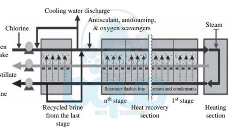
The Multi Stage Flash distillation MSF evaporator vessels is also referred to as flash stages or effects. What happens is that the high-salinity source water is heated to a temperature of 90 to 115°C (194 to 239°F) in a vessel (the heating section in the figure below) to create water vapor. The pressure in the first stage is maintained slightly below the saturation vapor pressure of the water. So when the high-pressure vapor created in the heating section enters into the first stage, its pressure is reduced to a level at which the vapor “flashes†into steam. Steam (waste heat) for the heating section is provided by the power plant co-located with the desalination plant. Each flash stage (effect) has a condenser to turn the steam into distillate. The condensers are equipped with heat exchange tubes, which are cooled by the source water that is fed to the condensers.

schematic multi stage flash distillation process
Entrainment separators (mist eliminators or demister pads) remove the high-salinity mist from the low-salinity rising steam. This steam condenses into pure water (distillate) on the heat exchange tubes and is collected in distillate trays. This is from where it is conveyed to a product water tank. Distillate flows from stage to stage and is collected at the last stage. The concentrate (brine) is generated in each stage and after collection at the last stage some of it typically is recycled to the source water stream in order to reduce the total volume of source water that must be collected by the intake for desalination. The recirculated brine flowing through the interior of the condenser tubes also removes the latent heat of condensation.
As a result, the recirculated brine is also preheated close to maximum operating temperature. Thereby recovering the energy of the condensing vapor and reducing the overall heating needs of the source water. This “brine recycle†feature has been adopted in practically all of the most recent MSF facility designs and allows significant improvement of the overall cost competitiveness of MSF installations. Each flash stage typically produces approximately 1 percent of the total volume of the desalination plant’s condensate. Since a typical MSF unit has 19 to 28 effects, the total MSF plant recovery (i.e., the volume of distillate expressed as a percentage of the total volume of processed source water) is typically 19 to 28 percent. For comparison, Reverse Osmosis seawater desalination SWRO plants have a recovery of 40% to 45%. The latest Multi Stage Flash Distillation technology has 45-stage units—i.e., can operate at 45% recovery. This feature allows it to compete with Reverse Osmosis systems in terms of recovery.
Historically, MSF was the first commercially available thermal desalination technology. It was applied to produce potable water on a large-scale, which explains its popularity. MSF plants represent over 80% of thermally desalinated water today. The gained output ratio GOR for MSF systems is typically between 2 and 8; the latest MSF technology has a GOR of 7 to 9. The pumping power required for the operation of the MSF systems is 2.0 to 3.5 kWh/m3 (7.6 to 13.3 kWh/1000 gal) of product water.
Reference: “Desalination Engineering” by Nikolay Voutchkov
What is Multi Effect Distillation MED
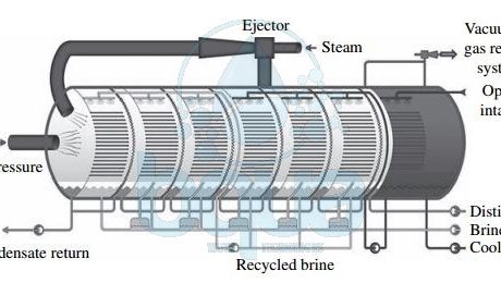
In Multi Effect Distillation MED systems, saline source water is typically not heated; cold source water is sprayed via nozzles or perforated plates over bundles of heat exchange tubes. This feed water sprayed on the tube bundles boils, and the generated vapor passes through mist eliminators. Which collect brine droplets from the vapor. The feed water that turned into vapor in the first stage (effect) is introduced into the heat exchange tubes of the next effect. Because the next effect is maintained at slightly lower pressure, although the vapor is slightly cooler, it still condenses into freshwater at this lower temperature.
This process of reducing the ambient pressure in each successive stage allows the feed water to undergo multiple successive boilings without the introduction of new heat. Steam flowing through the exchange tubes is condensed into pure water and collected from each effect. Heating steam (or vapor) introduced in the heat exchange tubes of the first effect is provided from an outside source by a steam ejector. The Multi Effect Distillation MED system shown in the figure below is also equipped with a brine recycle system. It allows the introduction of warmer-than-ambient water in the first effects of the system. Thereby reducing both the volume of feed water that must be collected by the plant intake system and the overall energy needs of the system.
The main difference between the Multi Effect Distillation MED and Multi Stage Flash Distillation MSF processes is that while vapor is created in an MSF system through flashing, evaporation of feed water in MED is achieved through heat transfer from the steam in the condenser tubes into the source water sprayed onto these tubes.

schematic multiple effect distillation process system
This heat transfer at the same time results in condensation of the vapor to freshwater. Multi Effect Distillation MED desalination systems typically operate at lower temperatures than MSF plants. Maximum brine concentrate temperature of 62 to 75°C versus 115°C) and yield higher GORs.
The newest Multi Effect Distillation MED technologies include vertically positioned effects (vertical tube evaporators). This may yield a GOR of up to 24 kg of potable water per kilogram of steam. Pumping power required for operation of Multi Effect Distillation MED systems is lower than that typically needed for MSF plants. It is equal to 0.8 to 1.4 kWh/m3/3.0 to 5.3 kWh/1000 gallons of product water. Therefore, Multi Effect Distillation MED is now increasingly gaining ground over MSF desalination. Especially in the Middle East, where thermal desalination is still the predominant method for producing potable water from seawater.
Reference: “Desalination Engineering” by Nikolay Voutchkov
What is Thermal Desalination Technology
All thermal desalination technologies apply distillation. This means heating the source water to produce water vapor, then condense into a low-salinity water. Since the energy for water evaporation is practically not dependent on the salinity concentration of the feed water source, thermal evaporation is very suitable for desalination of high salinity waters and brine. This is one of the reasons that thermal desalination has been widely adopted by Middle Eastern countries. Such countries are Saudi Arabia, Oman, Qatar, the United Arab Emirates, Bahrain and Kuwait. These countries use some of the most saline water bodies on the planet for water supply: Red Sea, Persian Gulf, Gulf of Oman, and Indian Ocean. At present, approximately 75% of the world’s thermal desalination plants are located in the Arabian Peninsula—half of those are in Saudi Arabia.
All thermal desalination plants have five key streams:
1- Source water (seawater, brackish water, or brine) used for desalination.
2- Steam needed for evaporation of the source water.
3- Cooling water to condense the freshwater vapor generated from the source water’s evaporation.
4- Low salinity distilled water (distillate).
5- And concentrate (brine), which contains the salts and other impurities separated from the source water.
The three most commonly used types of thermal desalination technologies are multi stage flash distillation (MSF), multi effect distillation (MED), and vapor compression (VC). Each of these classes of technology has evolved over the past 40-60 years toward improvements in efficiency and productivity. For example, MSF-BR is the abbreviation for a multi stage flash distillation process with brine recycle. MSF-BR reduces the source water volume and the steam needed for evaporation. Similarly, MED-TC stands for multi effect distillation with thermal compression. It is the state-of-the art MED technology. MVC is an acronym for mechanical vapor compression, a VC technology that can run without the need for an outside source of steam.

thermal desalination and evaporation distillation technologies
The three types of thermal technologies mainly differ by temperature and pressure at which source water is boiled to generate freshwater vapor. The oldest thermal evaporation process—MSF—boils water at near atmospheric pressure and a temperature close to 100°C (212°F). This type of process requires a large quantity of high-temperature steam. Multi Effect Distillation MED and Vapor Compression VC are newer thermal desalination technologies. They improved efficiency stems from the fact that water can be boiled at a lower temperature if the boiling process occurs at a pressure lower than the atmospheric pressure. Boiling water at a lower temperature allows the use of less and lower-quality steam for the production of the same volume of water.
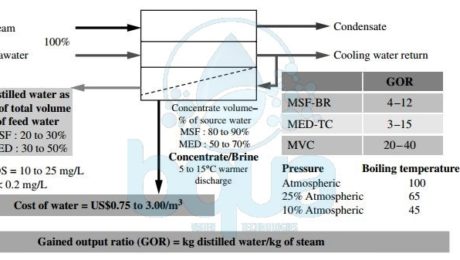
In Multi Effect Distillation MED vessels, the boiling process typically occurs at lower temperatures and pressures than in MSF systems. Vapor Compression VC thermal desalination systems operate at lower pressures than either Multi Stage Flash Distillation MSF or MED. which allows these systems to evaporate water at even lower temperatures and to generate their own steam rather than depend on outside steam sources. The ratio of the mass of low-salinity water (distillate) produced to the mass of heating steam used to produce this water is commonly referred to as the gained output ratio (GOR) or performance ratio.
Depending on the thermal desalination technology used, the site-specific conditions, and the source water quality, GOR typically varies between 4 and 40. Thermal desalination technologies produce 4 to 40 kg of freshwater using 1 kg of steam. The higher the GOR, the more efficient the technology, because it produces more freshwater from the same amount of steam. As seen in the figure, all thermal desalination technologies generate very low-salinity water (TDS in a range of 5 to 25 mg/L). This freshwater also has a very low content of pathogens and other contaminants of concern. Such as boron, bromides, and organics. Thermal desalination is most popular in the Middle East, where seawater desalination is typically combined with power generation. Therefore provides low-cost steam for the distillation process. Thermal desalination requires large quantities of steam. Most power plants outside the Middle East are not designed to yield significant amounts of waste steam as a side product of power generation. This is one of the key reasons why thermal desalination has not found wider application outside of the region.
Today, Seawater Reverse Osmosis SWRO dominates the global desalination market in term of capacities. They exceed both traditional thermal technologies (MSF and MED) which are common in the Middle East and North Africa regions. Seawater Reverse Osmosis SWRO is dominating worldwide over thermal technologies in terms of annual installed capacities. Yet the evolution of seawater reverse osmosis into the Gulf and MENA region, particularly in the Gulf of Arabia, has been slow. The reasons are higher feed water salinity affected by hydrocarbons and Red Tide events. Red tide is a phenomenon caused by algal blooms during which algae become so numerous that they discolor coastal waters. The algal bloom may also deplete oxygen in the waters and/or release toxins that may cause illness in humans and other animals.
Reference: “Desalination Engineering” by Nikolay Voutchkov
