Clean In Place – Membrane Cleaning CIP System
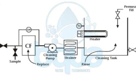
A Clean in place CIP system is a very effective method widely used by RO Systems manufacturers and operators to preserve and also clean fouled or scaled reverse osmosis system RO membranes. Using certain chemicals and following procedures guided by each RO Membrane manufacturers. With few exceptions, all reverse osmosis systems and other membrane systems are subject to fouling by one or more source water components and therefore require periodic cleaning. Clean In Place CIP Membrane cleaning is usually performed without removing membranes from the pressure vessels or the system. A Clean In Place CIP system is designed to prepare and recirculate chemical solutions through some of or all membrane modules at low pressure.
The CIP system can also be used to feed special membrane post treatment chemicals. Not to be confused with membrane system post treatment. Membrane performance require post-treatment equipment in some cases. The clean in place CIP system also serves to prepare and transfer membrane storage solutions, or preservatives. Membrane “pickling” solutions prevent microbial growth and in some cases prevent freezing when the membrane system is shut down for extended periods, typically more than a week. The clean in place system for a Reverse Osmosis System or Nano-Filtration system should be designed to accommodate all cleaning and membrane storage solutions expected to be used at the plant.
Inadequate clean in place CIP System procedures will result in ineffective cleaning results. We will discuss the major parameters of membrane cleaning followed by cleaning instructions from RO membrane manufacturers and step-by-step procedure. The major parameters are:
- Chemicals
- Temperature
- Flow rate
- Time
Clean In Place Chemicals
We won’t remove a carbonate scale with caustic or remove a biofilm with low pH. We must use the right chemical(s) to dissolve as much of the foulant / scalant as possible. Things that dissolve will leave the Reverse Osmosis System easily. It is the things that don’t dissolve which give us the problems. Please contact BQUA for more information about choosing the right chemical for your cleaning.
Clean In Place Temperature
Temperature affects chemical reactions. In general, the rate of most chemical reactions will double with every 10°C increase in temperature. In other words, we can get the job done quicker if the cleaning solution is warmer. If the cleaning solution temperature is less than 16°C (60°F), then cleaning will have no effect since the water is too cold. The cleaning solution temperature should be at least 21°C (70°F). Even better, get the temperature above 27°C (80°F).
Clean In Place Flow Rate
Flow rate is critical for removing fouling particles. It is unlikely that we will be able to dissolve particles completely. We, therefore, must physically remove them. We do this with turbulence. The higher the flow rate, the higher the turbulence. The higher the turbulence, the more particles removed.
Clean In Place Time
Frequently RO membrane manufacturers and chemical cleaning vendors recommend a one-hour cleaning. If the scalant/foulant is stubborn, some soaking time prior to, or after, we recommend circulating the solution. This is fine for lightly fouled/scaled elements. This may work if cleaning is initiated when the Normalized Permeate Flow NPF has dropped no more than 10-15%Â and/or the Differential Pressure DP across a stage has increased no more than 15-25%. And will not work if fouling/scaling has been allowed to progress. It is not unusual to have to clean severely fouled RO Membrane elements for 72 continuous hours. Use clean in place CIP monitoring sheets during a cleaning, and trending graphs following a cleaning, to determine when cleaning completes. Much more time than usually recommended may be required.
BQUA Clean In Place CIP System design
Clean In Place CIP System Procedure
RO membrane manufacturers provide the following clean in place CIP System procedures. This is followed by an illustrated, procedure which contains the most important points of a good clean in place membrane cleaning.
RO Membrane Element Cleaning and Flushing
The RO membrane elements in place in the pressure tubes are cleaned by recirculating the cleaning solution across the high-pressure side of the membrane at low pressure and relatively high flow. That’s when we use a CIP system. A general procedure for cleaning the Reverse Osmosis membrane elements is as follows:
- Flush the pressure tubes by pumping clean, chlorine-free product water from the cleaning tank (or equivalent source) through the pressure tubes to drain for several minutes.
- Mix a fresh batch of the selected cleaning solution in the cleaning tank, using clean product water. Circulate the cleaning solution through the pressure tubes for approximately one hour or the desired period of time. At a flow rate of 35 to 40 gpm (133 to 151 L/min.) per pressure tube for 8.0(20.3 cm) and 8.5(21.6 cm) inch pressure tubes, 15 to 20 gpm (57 to 76 L/min.) for 6.0(15.2 cm) pressure tubes, or 9 to 10 gpm (34 to 38 L/min.) for 4.0 inch pressure tubes.
- After completion of cleaning, drain and flush the cleaning tank; then fill the cleaning tank with clean product water for rinsing.
- Rinse the pressure tubes by pumping clean, chlorine-free product water from the cleaning tank (or equivalent source) through the pressure tubes to drain for several minutes.
- After rinsing the Reverse Osmosis system, operate it with the product dump. Open valves until the product water flows clean and is free of any foam or residues of cleaning agents (usually 15 – 30 minutes).
If the system shuts down for more than 24 hours, the best procedure for storage is soaking the element in an aqueous solution. With 20 percent, by weight, glycerine or propylene glycol and 1.0 percent, by weight, sodium bisulfite or SMBS Sodium Metabisulfite.
Example on Before and After CIP Chemical Membrane Cleaning in a Brackish Reverse Osmosis System
CIP System in Multi-Array Systems
For multi-array (tapered) systems the flushing and soaking operations can happen simultaneously in all arrays. You should carry out separately high flow re-circulation, however, for each array. So the flow rate is not too low in the first or too high in the last. This can be accomplished either by using one cleaning pump and operating one array at a time, or using a separate cleaning pump for each array.
RO membrane clean in place cip system overall procedure
- Published in Technology, Water Treatment
What is a Reverse Osmosis System – RO System Definition
A Reverse Osmosis System is basically the application of the reverse of the Osmosis process. Where pure water is produced out of brackish or seawater by applying a pressure to the concentrated salt solution above the applied and osmotic back pressures. An Industrial Reverse Osmosis System works the same way as illustrated. Net driving pressure (NDP) forces water through the membrane. In an operating Reverse Osmosis system, feed water is pressurized by a high pressure pump. Due to Net Driving Pressure (NDP), a portion of the feed water is forced through the Reverse Osmosis semipermeable membrane.
The membrane is completely impermeable (won’t allow passage) to particles and only slightly permeable to dissolved substances. The water that passes through the membrane is called permeate. Permeate usually has very few particles in it. Unless there is a membrane defect (hole) or other problem, any particles found in the permeate were produced there (either from bacteria or equipment). Permeate is also low in dissolved substances (a small amount of dissolved solids does pass through the membrane). Permeate, therefore, is a relatively high purity water. Figure below illustrates a Reverse Osmosis System in the format we have been using so far.
Reverse Osmosis System (RO System) Illustration
Reverse Osmosis System Operation and Flushing
We know that when we pressurize the feed water and water passes through the membrane, the feed water is concentrated. If the concentration in the feed water gets high enough, the osmotic back pressure will rise to eventually give us a Net Driving Pressure (NDP) of zero and the flow will stop. In a Reverse Osmosis System, then, we must flush away the dissolved substances from the membrane surface so that the osmotic back pressure won’t keep going up. This is different from the other filters that we usually work with. Most of the filters that we have dealt with in our lives have been “full flowâ€, “accumulative†types of filters. “Full flow†means that there is one stream in (feed water) and one stream out (filtrate). “Accumulative†means that the filtered “stuff†accumulate in or on the filter.
From coffee filters, to cartridge filters, to multimedia filters, this has been the case. The feed water goes in, the filter removes the “stuff†that we want to take. When the filter gets full, we backwash or replace the filter. Membrane systems can’t be full flow or accumulative. With an RO membrane, we are filtering out ions which have an osmotic pressure. What would happen if we continue to filter out dissolved substances which produce an osmotic back pressure? Answer: The process would stop.
A Reverse Osmosis System therefore, must have a flushing flow which carries away the dissolved and suspended substances. This waste stream is called concentrate. A Reverse Osmosis System (RO System), therefore, has one stream going into it (Feed Water), and two streams coming out (Permeate & Concentrate).
The following illustration also shows a Reverse Osmosis System with a 100 gpm (22.7 m3/hr) feed water flow. The Net Driving Pressure (NDP) supplied by a high pressure pump forces around 75% of the feed water through the membrane. The water, suspended particles, and dissolved substances which don’t go through the membrane are concentrated and exit the Reverse Osmosis System as concentrate.
Reverse Osmosis System Operation Example
Reverse Osmosis System Contaminants Removal
Most water constituents retains on the feed side of the Reverse Osmosis membrane depending on their size and electric charge. While the purified water (permeate) passes through the membrane. Figure below illustrates the sizes and types of solids removed by Reverse Osmosis membranes as compared to other commonly used filtration technologies. RO membranes can reject particulate and dissolved solids of practically any size. However, they do not reject well gases, because of their small molecular size. Usually Reverse Osmosis membranes remove over 90 percent of compounds of 200 daltons (Da) or more. One Da is equal to 1.666054 × 10⁻²⁴ g. In terms of physical size, RO membranes can reject well solids larger than 1 (Angstrom) Å. This means that they can remove practically all suspended solids, protozoa (i.e., Giardia and Cryptosporidium), bacteria, viruses, and other human pathogens contained in the source water. Reverse Osmosis membranes are designed to primarily reject soluble compounds (mineral ions) while retaining both particulate and dissolved solids.
BQUA Reverse Osmosis RO Membrane Contaminant Removal
The structure and configuration of Reverse Osmosis membranes is such that they cannot store and remove from their surface large amounts of suspended solids. If left in the source water, the solid particulates would accumulate and quickly plug (foul) the surface of the Reverse Osmosis membranes. Not allowing the membranes to maintain a continuous steady-state desalination process. Therefore, the suspended solids (particulates) in desalination feed water must be removed before reaching the RO membranes.
Over the past 20 years, RO membrane separation has evolved more rapidly than any other desalination technology. Mainly because of its competitive energy consumption and water production costs. Brackish Water Reverse Osmosis System (BWRO) yields the lowest overall production costs of all the desalination technologies. It is also important to note that the latest Multi-Effect Distillation MED projects built over the last 5 years have been completed at costs comparable to those for similarly sized Seawater Reverse Osmosis plants. Seawater Reverse Osmosis (SWRO) desalination – for the majority of medium and large projects – is usually is more cost competitive than thermal desalination technologies.
Example of an Industrial Brackish Water Reverse Osmosis System BWRO
- Published in Technology, Water Treatment
What is a Pressure Membrane / Pressure-Driven Membrane
The pressure membrane processes are:
– Reverse osmosis (RO)
– Nanofiltration (NF)
– Ultrafiltration (UF)
– Microfiltration (MF)
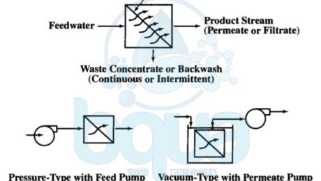
A pressure membrane is a membrane that functions by applying a pressure. A pressure membrane is permeable to water but not to substances which are rejected and removed. All membranes including any pressure-driven membrane separate feedwater into two streams: permeate and concentrate streams. The permeate (for RO, NF, or UF) or filtrate (for MF) stream passes through the membrane barrier. The concentrate (or retentate) stream contains the substances removed from the feedwater after the pressure membrane barrier rejects it.
Actually, the driving force for these pressure membrane processes may come from (1) a pressurized feedwater source with the membranes installed in pressure vessels, called modules. Or (2) a partial vacuum in the filtrate/permeate flow stream caused by use of a filtrate/permeate pump or gravity siphon. The vacuum-driven processes typically apply to MF and UF only and have membranes submerged or immersed in nonpressurized feedwater tanks.
pressure membrane process using feed or permeate pumps
Pressure membrane processes are designed for cross-flow or dead-end operating modes. In the cross-flow mode, the feed stream flows across the pressure membrane surface. And permeate (or filtrate) passes through the pressure-driven membrane tangential to the membrane surface. Moreover, cross-flow operation results in a continuously flowing waste stream. A cross-flow system design sometimes contain a concentrate recycle. Also with a reject stream (feed-and-bleed mode). Many MF and UF systems treating relatively low turbidity waters are also designed to operate in a dead-end flow pattern where the waste concentrate stream is produced by an intermittent backwash. The figure below shows the relative removal capabilities for pressure-driven membrane processes and compares these processes with media filtration.
pressure membrane processes RO NF UF MF difference pore size rejection
In fact, MF and UF separate substances from feedwater through a sieving action. Separation depends on the pressure membrane pore size and interaction with previously rejected material on the membrane surface. Furthermore, NF and RO separate solutes by diffusion through a thin, dense, permselective (or semi-permeable) membrane barrier layer, as well as by sieving action. The required pressure membrane feed pressure generally increases as removal capability increases.
- Published in Technology, Water Treatment


