


What is Turbidity Definition
Turbidity is a parameter which measures the content of particulate foulants in the reverse osmosis feed water source. Turbidity can also be defined as the measurement of the light scattering properties of particles in suspension. The instrument used to measure turbidity is called a turbidimeter or turbidity meter.
The principle of turbidity meters is that suspended particles will block or reflect light. There are several different types of turbidity meters, but they are all based on the principle of particles blocking or reflecting light. Let’s look at reflected light first.
If there are no particles suspended in a sample, light will pass through the sample in a straight line. If a photocell (photoreceptor) is located at 90 degrees to the light path, no light will reach the photocell and the turbidity will read zero.

If particles present in a sample, the light will be reflected off of the surfaces of the particles and will be scattered at different angles. A photoreceptor at 90 degrees from the source of light will pick up light that is scattered and a turbidity measurement greater than 0 will be obtained.

The unit of measurement for turbidity is the NTU or the JTU or the FTU. There is no correlation between NTU and JTU and FTU. The term nephelometric indicates that this is a light-interference analytical technique. NTU is the measurement unit for light scattering. Some on-stream turbidity meters also use the light-scattering principle. A common one is called the surface scatter turbidimeter.

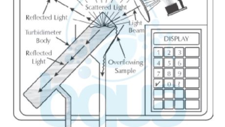
For a surface-scatter turbidimeter, the sample with suspended particles is passed up through a tube. A light source is shining on the surface of the liquid as it flows over the top of the tube. A photocell is located above the surface of the water. If there are no particulates in the water, the light beam is absorbed by the black tube and the black interior of the enclosure. If they are present, they scatter light as they surface (This is why this technique is called surface-scatter). The photocell picks up the scattered light and displays the reading in NTU.
There is another type of turbidimeter which doesn’t measure the light scattered but rather the reduction in transmitted light. In this case the full beam is received by the photocell. Full-beam reception equates to clean water and no turbidity.
  
If particles are present, less light reaches the photocell. This, then, is displayed as a turbidity reading, in JTU (Jackson Turbidity Unit, named after the man who created the standard candle which was originally used as the source of the light). Figure below illustrates particulates in the sample scattering, and therefore blocking, the light beams.

The turbidity level in the source of water is indicative of the content of clay, silt, suspended organic matter, and microscopic aquatic life. Such as phyto- and zooplankton. It is expressed in Nephelometric Turbidity Units (NTU) and Formazin Nephelometric Unit (FNU). The turbidity of open ocean and surface brackish water can vary between 0.1 and several hundred NTU, although under normal dry weather conditions, it is typically between 0.5 and 2.0 NTU. Rain events, algal blooms, storms, snow melt, river discharges, and human activity (such as wastewater discharges, ship traffic, etc.) can cause significant turbidity increases and variations. Usually, water that is saline with a turbidity below 0.05 NTU causes very low particulate fouling of the reverse osmosis membrane. Most RO membrane manufacturers have a maximum feed raw water turbidity of 1.0 NTU, although this level is relatively high in practical terms. Usually, filtered water turbidity below 0.1 NTU is desirable.
Although turbidity is a good measure of the overall content of particulates in the source water, on its own it is not an adequate parameter to characterize water’s potential for particulate or other fouling. Turbidity measurement does not provide information regarding the type and particle size in the source feed water and does not measure the constitution of dissolved organic and inorganic foulants. The size of particles contained in the source water matters because RO membrane feed and concentrate spacers, through which the saline raw water is distributed inside the membranes, are of limited width (typically 0.7 to 0.9 mm).
Even with these problems, turbidity measurements can be valuable trending indications for monitoring RO unit feed water. Most manufacturers require that the feed water to an RO unit be less than 1.0 NTU. Turbidity is almost always measured on feed waters which are processed through a clarifier. Clarifiers are usually found at facilities with a surface water source and no prior municipal treatment. In this case turbidity is frequently measured before and after the clarifier to monitor the performance of the clarifier. In a few cases, turbidity is measured before and/or after a multimedia filter to monitor performance of this piece of equipment. Turbidity or TSS measurements alone are insufficient to tell us about the fouling potential of our feed water. They must be used in conjunction with SDI (Silt Density Index).
What is Sedimentation ?
After coagulation occurs followed by a flocculation process before entering a sedimentation basin / clarifier. Flocculated particles enter a sedimentation basin and begin to settle. Particles also referred to as sediments agglomerate to form larger flocs. This process is called sedimentation. When flocs / particles enter a basin and then start to settle, particles’ settling velocities change as particles agglomerate and form larger floc. Because the settling properties of flocculant suspensions cannot be formulated, a clarifier / sedimentation basin performance cannot be accurately predicted. However, for new plants, settling rates can be estimated from batch settling data developed with laboratory jar tests. For expanding existing plants, settling rates can be derived from evaluating the performance of existing basin during various influent water quality conditions. These evaluations often allow for increasing rates for existing basins and establishing higher rates, as compared to published guidelines, for new basins. In an ideal continuous flow basin, sedimentation would take place as it does in the laboratory jar. However, in a real clarifier, wind, temperature density currents, and other factors cause short-circuiting, disruption of flow patterns, breakup of floc, and scouring of the settled sludge. The designer must learn as much as possible about the settling properties of the flocculated solids and then design to match these characteristics. When the designers do not have access to source water data, it is best to select design criteria known to have worked in similar applications, either from personal experience or from regulatory guidelines.
Sedimentation Design Approach
The primary approach in designing conventional sedimentation basins is to select a design overflow rate for maximum expected plant flow. This rate may be chosen based on all units being in service or on one unit being out of service, to allow for redundancy. After selecting a rate, the designer should determine the number of units needed and select the type of sludge collection and removal equipment. The sludge equipment for removing may limit basin dimensions, which could establish the size and num. of units. With the number of basins selected, the designer should proceed to design inlet and outlet conditions and finalize dimensions to suit all design parameters and site conditions. The following are suggested guidelines for the various design parameters.
Sedimentation Overflow Rates
Hydraulic overflow rate is the primary design parameter for sizing sedimentation basins. This rate is defined as the rate of inflow Q divided by the tank surface area A. Units are typically rated in gallons per day per square foot, gallons per minute per square foot, or cubic meters per hour per square meter. Acceptable rates vary with the nature of the settling solids, water temperature, and hydraulic characteristics of the settling basin.
After evaluation of both cold & warm water loading rates, the design rate is based on whichever is more critical. Plant flow variations between warm and cold water periods often allow selection of higher rates for summer operation than the typical suggested loading rates. Overflow rates can also be selected based on pilot studies. Piloting of conventional settling basins is not especially reliable, but it is often done using tube settlers. Data from such studies, along with jar testing, are often useful in design. Pilot testing of other types of settling, especially proprietary processes, is useful and is recommended.
Detention Time
Which is the flow rate divided by tank volume, is usually not an important design parameter. Many regulatory agencies (e.g., Great Lakes, 2003), however, still have a requirement for detention periods of 4 h. It is likely that this detention requirement is a carryover from the days of manually cleaned basins designed to provide the sludge storage zone. These basins were often 15 to 16 ft (4.6 to 4.9 m) deep or greater and operated so that more than one-half the volume could be filled with sludge before being cleaned. Real time could vary from 4 h when clean to less than 2 h just before cleaning. Modern designs with mechanical sludge removal equipment need not provide a sludge zone, and deep basins with long detention times are no longer required. Conventional basins with detention times of 1.5 to 2.0 h provide excellent treatment.
Basin Depth and Velocities
In theory, basin depth should not be an important parameter either, because settling is based on overflow rates. However, in practice, it is important because it affects flow-through velocity. Flow-through velocities must be low enough to minimize scouring of settled floc blanket. Velocities of 2 to 4 ft/min (0.6 to 1.2 rn/min) usually are acceptable for basin depths of 7 to 14 ft (2.1 to 4.3 m), the hallower depths often used with multiple-tray basins. Single-pass basins are generally deeper, to offset the effects of short-circuiting from density and wind currents.

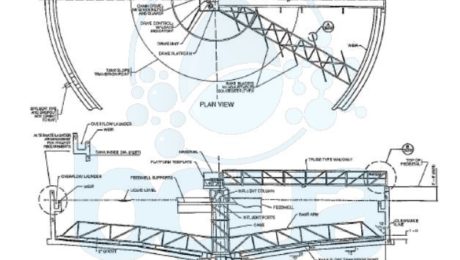
Circular Sedimentation Basin / Clarifier design
What is Clarification ?
Clarification has more than one application in water treatment. Its usual purpose in a conventional treatment process is to reduce the solids load after coagulation and flocculation. A second application, a process called plain sedimentation, is removal of heavy settleable solids from turbid water sources to lessen the solids on treatment plant processes. Material presented deals primarily with settling flocculated solids. One way of designing the clarification process is to maximize solids removal by clarification, which generally requires lower clarifier loadings and larger, more costly units. Alternatively, the clarifier may be designed to remove only sufficient solids to provide reasonable filter run times and to ensure filtered water quality. This latter approach optimizes the entire desalination plant and generally leads to smaller, less expensive facilities. Typical loading rates suggested in other articles or by regulatory guidelines are generally conservatively selected to provide a high-clarity settled water rather than optimization of the clarifier – filter combination.
The clarifier falls into two basic categories: those used only to remove settleable solids, either by plain sedimentation or after flocculation. And those that combine flocculation and clarification processes into a single unit. The first category also includes conventional sedimentation basins and high-rate modifications such as tube or plate settlers and dissolved air flotation (DAF). The second category does include solids contact units such as the sludge blanket clarifier and slurry recirculation clarifier. Also included in this category is contact clarification in which flocculation and clarification take place in a coarse granular media bed.
Conventional Clarification Design
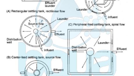
Most sedimentation basins also known as a clarifier used in water treatment are the horizontal-flow type in rectangular, square, or circular design. Both long, rectangular basins and circular basins are commonly used; the choice is based on local conditions, economics, and personal preference. Camp (1946) states that long, rectangular clarifier exhibit more stable flow characteristics and therefore better sedimentation performance than very large square basins or circular tanks. Basins were originally designed to store sludge for several months and were periodically taken out of service for manual cleaning by flushing. A clarifier is now designed to be cleaned with mechanical equipment on a continuous or frequent schedule.
Please contact us for more information and water treatment solutions. Or learn more about our products.

Sedimentation Basin a.k.a Clarifier Design
Concentration Polarization
If there are fouling feed water colloidal silica particles, these sub-micron particles will not be trapped in feed water spacer. They may be deposited evenly on the surface of the membrane, causing a problem in all stages. Usually the colloidal particles create more of a last stage problem. Colloidal fouling occurring in the last stage is likely due to agglomeration of sub-micron particles into larger fouling particles due to surface charge neutralization of the particles by double- and triple-charged cations concentrated at the surface of the Reverse Osmosis RO membrane. Due to concentration polarization, colloidal fouling is more likely at the surface of the membrane and in the rear end of a Reverse Osmosis System.

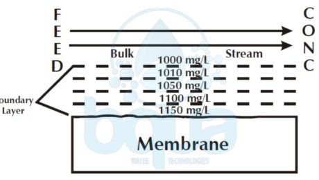
concentration polarization boundary layer on RO membrane surface
Whenever water flows past a solid, there is some attraction and adhesion between the water and the solid. Adhesion between the water and the solid surface causes the water molecules closest to the surface to be stationary relative to it. The farther from the surface water molecules are, the less attraction and adhesion, and therefore the more velocity relative to the surface. Right at the membrane surface, there is no tangential flow. This is the boundary layer When tiny particles deposit on the membrane surface, there is no tangential flow to sweep them off.

concentration polarization on reverse osmosis membrane
Additionally, the flow of water through the RO membrane, when the high pressure pump is on, will tend to hold them there Not only are feed water particles deposited on the membrane in this way. They may also be grown there. This is likely caused by concentration polarization. Concentration polarization is a function of the boundary layer. It refers to an increased salt concentration at the RO membrane surface. A portion of the feed water passes through the boundary layer and through the membrane.
The water passes through the membrane. The dissolved components do not readily pass through the membrane. The dissolved components, therefore, are left behind at the membrane surface. This causes the salt concentration (TDS, Total Dissolved Solids concentration) to be higher at the membrane surface If the boundary layer had tangential flow and was turbulent, the incoming feed water would mix up the boundary layer and the boundary layer would have the same concentration as the bulk stream.

concentration polarization and total dissolved salts
The boundary layer, however, has no tangential flow. The salts concentrate at the surface. Fortunately, the dissolved substances can diffuse away from the membrane. Recall that diffusion is the movement of dissolved substances from higher concentration to lower concentration. So if we could look into the boundary layer, we would see that, due to diffusion, the salt concentration diminishes from the surface of the membrane to the top of the boundary layer.
At the top of the boundary layer, the concentration is the same as the bulk stream The higher the water flux through the membrane, the more salts collect at the membrane surface, and therefore the higher the salt concentration at the membrane surface. Typically the TDS at the membrane surface is 10% – 15% higher than that measured in the bulk stream. If water flux is increased, a higher TDS will occur at the surface. As we will see below, concentration polarization not only impacts dissolved solids. It may also affect suspended solids.
