


What is Dissociation Constant Definition
Dissociation Constant demonstrates the maximum range to which an element or substance would dissociate into ions. The Dissociation Constant referred to as “K” is equal to the product of the concentrations of the corresponding ions:
K = [H+] x [OH-]
The dissociation constant for a compound such as sodium chloride is very large since the ions are almost totally dissociated (exist as separate cations and anions). Dissociation constants for compounds which do not readily dissociate (separate) are small.
Highly Soluble Salts <——-> Large Dissociation Constant
Slightly Soluble Salts <——> Small Dissociation Constant
Most ionic compounds will dissociate to some extent. Even water will slightly dissociate as described by the equation below.
H2O —-> (H+) + (OH-)
The dissociation constant for water is found by multiplying the concentrations of the hydrogen ion (H+) and the hydroxide ion (OH-). The brackets in the equation indicate that we are dealing with concentrations expressed in molarity. Scientists found that the product of concentration of the two ions is 1.0 x 10⁻¹⁴ at standard conditions.
K = [H+] x [OH-] = 1.0 x 10^-14
If we are dealing with pure water, we know that the concentration of H+ and OH- must be the same since one of each is required to make a water molecule.
[H+] = [OH-]
Since,
(H+) + (OH-) —–> H2O
Therefore, if the concentrations of the ions multiplied together are equal to 1.0 x 10^-14 and the concentrations of each ion are the same, we know that the concentration of each ion is 1.0 x 10^-7. Remember, when we multiply numbers with exponents, we add the exponents together.
[H+] x [OH-] = 1.0 x 10^-14
1.0 x 10^? x 1.0 x 10^? = 1.0 x 10^-14
[H+] and [OH-] are equal:
[H+] = [OH-] = 1.0 x 10^-14
1.0 x 10^-7 [H+] x 1.0 x 10^-7 [OH-] = 1.0 x 10^-14
If we add some hydrochloric acid (HCl) to the pure water, the concentration of hydrogen ions will increase since HCl is almost completely dissociated.
HCl + H2O —–> H+* + Cl- + H2O
*Concentration of H+ is increased by the addition of HCl
As the concentration of hydrogen ions increases, the concentration of hydroxide ions decreases. This is because the dissociation constant (product of the H+ concentration multiplied by the OH- concentration) for water does not change. It is a basic chemical characteristic just like density, boiling point, freezing point, etc.
[H+] x [OH-] = 1.0 x 10^-14
As the concentration of H+ goes up, the negative exponent on the concentration value goes down. In our example below, it goes from -7 to -5. The hydroxide exponent therefore must go from -7 to -9. Remember, the dissociation constant does not change. The product of the two concentrations (sum of the exponents) must always equal -14.
Example:
Pure Water
1.0 x 10^-7 x 1.0 x 10^-7 = 1.0 x 10^-14
With the addition of acid
1.0 x 10^-5* x 1.0 x 10^-9 = 1.0 x 10^-14**
*This number is larger due to the addition of acid.
**This number must remain the same.
In the same manner, if we add sodium hydroxide (NaOH) to pure water, the OH- concentration will increase. If the OH- concentration increases, the H+ concentration must decrease.
Now we can see that with water we can have one of three conditions. First, we can have a condition in which there are an equal number of H+ and OH- ions. Water in this state is said to be neutral. Second, we can have a condition in which we have more H+ than OH- ions. This condition is called acidic. Third, we can have a condition in which there are more OH- than H+ ions. This condition is called basic or alkaline.
[H+] > [OH-] —–> Acidic
[H+] = [OH-] —–> Neutral
[H+] < [OH-] —–> Alkaline
Qué es una definición de filtro de cartucho
Un filtro de cartucho es un microfiltro fino de tamaño nominal de 1 a 25 um (micras) hecho de fibras de plástico delgadas u otros medios de filtración fina que se instala alrededor de un tubo central para formar un cartucho de tamaño estándar. Los filtros de cartucho a menudo se utilizan como el único dispositivo de detección entre los pozos de admisión y el sistema de ósmosis inversa. Esto es en el caso de las plantas de desalinización de agua de mar y salobres con entradas de pozo que producen agua de alta calidad. Los filtros de cartucho son instalaciones de protección de membrana RO en lugar de dispositivos de detección; el objetivo principal al que sirven es capturar partÃculas en el agua de la fuente pretratada que puede haber pasado a través de los sistemas de pretratamiento aguas arriba con el fin de evitar daños o incrustaciones prematuras de las membranas de OI.
Aunque los cartuchos filtrantes de polipropileno enrollados (hilados) son los más comúnmente utilizados para aplicaciones de agua de mar y aguas salobres. Otros tipos, como los cartuchos fundidos por soplado o plisados ​​de otros materiales también han encontrado aplicación. Los filtros de cartucho estándar para plantas de desalinización RO tienen tÃpicamente 101,6 a 1524 cm (40 a 60 in) de largo. Y se instalan en recipientes a presión horizontales o verticales (carcasas de filtros). Los cartuchos están clasificados para la eliminación de partÃculas de 1, 2, 5, 10 o 25 um, y el tamaño más utilizado es de 5 um.

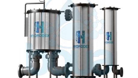
Hydrodex – Cartridge Filter – Filtro De Cartucho
Ejemplo de filtros de cartucho: filtro de cartucho Hydrodex
Es útil mencionar que Hydrodex es uno de los lÃderes del mercado en la industria de la filtración. Hydrodex fabrica un filtro de cartucho premium hecho de polÃmero reforzado con vidrio (GRP).
Consideraciones de planificación y diseño
Los filtros de cartucho normalmente se instalan aguas abajo del sistema de filtración de medios granulares. Eso es en caso de que tal sistema se use para pretratamiento para capturar arena fina, partÃculas y sedimentos que pueden estar contenidos en el agua pretratada. Cuando la fuente de agua de mar es de muy alta calidad, un Ãndice de densidad de sedimentos (SDI) por debajo de 2, y no necesita eliminación de partÃculas por filtración antes de la desalinización. En este caso, los filtros de cartucho se utilizan como el único dispositivo de pretratamiento. Sirviendo como una barrera para capturar limo fino y partÃculas que ocasionalmente pueden ingresar al agua de la fuente durante la puesta en marcha de las bombas de los pozos de admisión o debido a fallas en los equipos o tuberÃas de admisión.
Una indicación tÃpica de si el sistema de pretratamiento de una planta de desalinización determinada funciona adecuadamente es la reducción de SDI a través de los filtros de cartucho. Si el sistema de pretratamiento tiene un buen rendimiento, la SDI del agua fuente aguas arriba y aguas abajo de los filtros del cartucho es aproximadamente la misma. Si los filtros del cartucho reducen consistentemente la IDE de la fuente de agua filtrada en más de 1 unidad, esto significa que el sistema de pretratamiento aguas arriba no está funcionando correctamente. A veces, la SDI del agua fuente aumenta cuando pasa a través de los filtros de cartucho. Esto casi siempre ocurre porque los filtros del cartucho no se han diseñado correctamente o no funcionan bien y proporcionan las condiciones para el crecimiento de microorganismos bioincrustantes en y dentro de los filtros.
Una cuestión frecuentemente debatida es si los filtros de cartucho son necesarios aguas abajo de los sistemas de pretratamiento con membrana MF o UF. Teniendo en cuenta que los poros del filtro de cartucho son de uno a dos órdenes de magnitud más grandes que los de los filtros de membrana. La respuesta a esta pregunta depende en gran medida de la calidad del material de fibra de la membrana de pretratamiento y del tipo de patrón de flujo a través del sistema de pretratamiento.
Para sistemas de filtración UF o MF que tienen un patrón de flujo directo. Donde las bombas de alimentación de la planta de desalinización transportan agua directamente a través del sistema de pretratamiento de la membrana sin un bombeo provisional. Las membranas de pretratamiento tienen más probabilidades de estar expuestas a sobretensiones. Si el material de fibra de las membranas de pretratamiento es débil y se rompe fácilmente bajo condiciones de sobretensiones de presión, es más probable que el sistema de pretratamiento experimente roturas de fibra. Las fibras de membrana rotas liberarán pequeñas cantidades de partÃculas en el agua de alimentación de RO. Lo que podrÃa causar un ensuciamiento acelerado de la membrana a menos que se capture mediante filtración de cartucho.
Además, si las fibras de membrana rotas liberan partÃculas agudas contenidas en el agua fuente, estas partÃculas también podrÃan dañar las membranas de OI. Las partÃculas afiladas de la cáscara rota pueden llegar al agua pretratada con UF o MF si el plancton de mariscos contenido en el agua de la fuente pasa a través de las micropantallas. Crece a organismos de crustáceos adultos (por ejemplo, percebes) en las paredes de la estación de bombeo de alimentación del sistema de pretratamiento. Y libera porciones de conchas que se han roto en partÃculas pequeñas y afiladas por las bombas de alimentación.
Las partÃculas de la cubierta se presurizarán sobre las fibras del filtro de membrana UF / MF, causando pinchazos y finalmente entrando en el flujo filtrado. En tales casos, el uso de filtros de cartucho aguas abajo del sistema de pretratamiento de membrana es una práctica de ingenierÃa prudente. Los filtros de cartucho funcionan bajo presión, y la presión diferencial a través de ellos se controla para ayudar a determinar cuándo deben reemplazarse los cartuchos de filtro. Además, los puertos de muestra con válvula deben instalarse inmediatamente aguas arriba y aguas abajo de los recipientes del filtro de cartucho para el muestreo y la supervisión de la calidad del agua (incluidas las pruebas de campo SDI).
Los sistemas de filtración de cartuchos están diseñados para velocidades de carga hidráulica de 0.2 a 0.3 L / s por 250 mm (3 a 5 gal / min por 10 in) de longitud. Normalmente se proporciona una capacidad de filtración adicional para permitir el reemplazo de los cartuchos sin interrupción de la producción de agua. Los recipientes a presión generalmente están construidos de acero inoxidable dúplex para instalaciones de RO de agua de mar.
La caÃda de presión en un filtro de cartucho limpio generalmente se especifica como inferior a 0,2 bar (2,8 lb / in2). Comúnmente, los cartuchos se reemplazan cuando la presión diferencial del filtro alcanza 0.7 a 1.0 bar (10.1 a 14.5 lb / in2). El tiempo de funcionamiento antes del reemplazo depende de la calidad del agua de la fuente y del grado de pretratamiento. Normalmente, se necesita un reemplazo de filtro de cartucho una vez cada 6 a 8 semanas. Sin embargo, si la fuente de agua de mar es de muy buena calidad, es posible que los filtros de cartucho no necesiten reemplazo durante 6 meses o más.
Para sistemas de OI donde puede anticiparse arena en el agua de alimentación. Los cartuchos de soplado en fusión rÃgidos o filtros de cartucho con un solo extremo abierto y doble junta tórica en la boquilla de inserción (en lugar de cartuchos convencionales con dos extremos abiertos) se utilizan comúnmente. Los filtros de inserción de un solo extremo abierto tienen un asiento positivo y una placa de inserción. Lo cual no permite la deformación del cartucho de filtro bajo presión causada por el empaque de arena. Los filtros de cartucho de doble apertura se mantienen en su lugar mediante una placa de presión con resorte.
Ejemplo de diseño de un filtro de cartucho
Este ejemplo presenta el tamaño y la configuración del sistema de filtración de cartucho para una planta de desalinización de agua de mar de 40,000 m3 / dÃa (10.6 mgd). Con un flujo total de la toma de agua de la planta de 98,440 m3 / dÃa (26 mgd).
| Flujo de alimentación de diseño, Qin | 98,440 m3/day = 1140 L/s |
| Cartucho de material de filtro | Polipropileno Plisado |
| Tamaño del filtro de cartucho | 5 um (micron) |
| Longitud del filtro de cartucho, Lcf | 1016 mm (40 in.) |
| Tasa de carga de diseño seleccionada, DLR | 0.25 L/s per 250 mm |
| Cantidad de filtros de cartucho necesarios | Qin/[DLR x (Lcf/250)] (8.1) = 1140/[0.25 x (1016/250)] = 1122 |
| Cantidad de recipientes de cartucho | 6 (selected to match RO trains) |
| Material del recipiente del cartucho | Glass-reinforced plastic |
| Número de cartuchos de filtro por recipiente | 1122/6 = 187 (selected 180) |
| Tasa de carga del filtro de cartucho real | 1140/[180 x 6 x (1016/250)] = 0.26 L/s per 250 mm (4.2 gal/min per 10 in.) |
En resumen, el sistema de filtración de cartuchos para la planta de desalinización de 40,000 m3 / dÃa (10.6 mgd) constará de seis recipientes de cartucho. Cada uno de los cuales contendrá 180 filtros de cartucho de tamaño 5 μm y longitud de 40 pulg.
What is a Cartridge Filter Definition
A Cartridge filter is a fine microfilter of nominal size from 1 to 25 um (micron) made of thin plastic fibers or other fine filtration media that is installed around a central tube to form a standard-size cartridge. Cartridge Filters are often used as the only screening device between the intake wells and the Reverse Osmosis system. This is in case of brackish and seawater desalination plants with well intakes producing high-quality source water. Cartridge filters are RO membrane protection facilities rather than screening devices; the main purpose they serve is to capture particulates in the pretreated source water that may have passed through the upstream pretreatment systems in order to prevent damage or premature fouling of the RO membranes.
Although wound (spun) polypropylene filter cartridges are most commonly used for seawater and brackish water applications. Other types, such as melt-blown or pleated cartridges of other materials have also found application. Standard cartridge filters for RO desalination plants are typically 101.6 to 1524 cm (40 to 60 in.) long. And are installed in either horizontal or vertical pressure vessels (filter housings). Cartridges are rated for removal of particles of 1, 2, 5, 10, or 25 um, with the most frequently used size being 5 um.

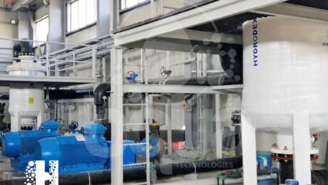
Fig. 1: Example on Cartridge Filter Housing Manufacturer: Hydrodex Filter Housings

Fig. 2: Hydrodex FRP cartridge filter housing low to medium flow rates
It is useful to mention that Hydrodex is one of the market leaders in the filtration industry. Hydrodex manufactures a premium cartridge filter made of Glass Reinforced Polymer (GRP).
Cartridge Filter Planning and Design Considerations
Cartridge filters are typically installed downstream of the granular media filtration system. That is in case such a system is used for pretreatment to capture fine sand, particles, and silt that may be contained in the pretreated water. When the source seawater is of very high quality – a silt density index (SDI) below 2 – and does not need particulate removal by filtration prior to desalination. In this case cartridge filters are used as the only pretreatment device. Serving as a barrier to capture fine silt and particulates that can occasionally enter the source water during the start-up of intake well pumps or due to failure of intake equipment or piping.

Cartridge Filter in Horizontal Orientation
A typical indication of whether the pretreatment system of a given desalination plant operates properly is the SDI reduction through the cartridge filters. If the pretreatment system performs well, then the SDI of the source water upstream and downstream of the cartridge filters is approximately the same. If the cartridge filters consistently reduce the SDI of the filtered source water by over 1 unit. This means that the upstream pretreatment system is not functioning properly. Sometimes the SDI of the source water increases when it passes through the cartridge filters. This almost always occurs because the cartridge filters have not been designed properly or are malfunctioning and providing conditions for growth of biofouling microorganisms on and within the filters.
A frequently debated question is whether cartridge filters are needed downstream of MF or UF membrane pretreatment systems. Taking into consideration that the cartridge filter pores are one to two orders of magnitude larger than those of the membrane filters. The answer to this question is highly dependent on the quality of the pretreatment membrane’s fiber material. And the type of flow pattern through the pretreatment system.
For UF or MF filtration systems that have a direct flow-through pattern. Where the desalination plant feed pumps convey water directly through the membrane pretreatment system without an interim pumping. The pretreatment membranes are more likely to be exposed to pressure surges. If the fiber material of the pretreatment membranes is weak and breaks easily under pressure surge conditions, the pretreatment system is more likely to experience fiber breaks. Broken membrane fibers will release small amounts of particles into the RO feed water. Which could cause accelerated membrane fouling unless it is captured by cartridge filtration.
In addition, if the broken membrane fibers release sharp particles contained in the source water, these particles could also damage the RO membranes. Sharp broken-shell particles may find their way into the UF or MF pretreated water if shellfish plankton contained in the source water passes through the microscreens. Grows to adult shellfish organisms (e.g., barnacles) on the walls of the pretreatment system feed pump station. And releases portions of shells that have been broken into small, sharp particles by the feed pumps.
The shell particles will be pressurized onto the UF/MF membrane filter fibers, causing punctures and ultimately entering the filtered flow. In such cases, the use of cartridge filters downstream of the membrane pretreatment system is a prudent engineering practice. Cartridge filters are operated under pressure, and the differential pressure across them is monitored to aid in determining when filter cartridges should be replaced. In addition, valved sample ports should be installed immediately upstream and downstream of the cartridge filter vessels for water quality sampling and monitoring (including SDI field testing).
Cartridge filtration systems are designed for hydraulic loading rates of 0.2 to 0.3 L/s per 250 mm (3 to 5 gal/min per 10 in.) of length. Additional filtration capacity is normally provided to allow replacement of cartridges without interruption of water production. Pressure vessels are typically constructed of duplex stainless steel for seawater RO installations.
The pressure drop across a clean cartridge filter is usually specified as less than 0.2 bar (2.8 lb/in2). Commonly, cartridges are replaced when the filter differential pressure reaches 0.7 to 1.0 bar (10.1 to 14.5 lb/in2). The operational time before replacement depends on the source water quality and the degree of pretreatment. Typically, a cartridge filter replacement is needed once every 6 to 8 weeks. However, if the source seawater is of very good quality cartridge filters may not need replacement for 6 months or more.
For RO systems where sand in the feed water might be anticipated. Rigid meltblown cartridges or cartridge filters with single open ends and dual O-rings on the insertion nipple. Rather than conventional cartridges with dual open ends, are commonly used. The single-open-end insertion filters have positive seating and an insertion plate. Which does not allow deformation of the filter cartridge under pressure caused by sand packing. Double-open-end cartridge filters are held in place by a spring-loaded pressure plate.
Design Example of a Cartridge Filter
This example presents the sizing and configuration of the cartridge filtration system for a 40,000 m3/day (10.6 mgd) seawater desalination plant. With a total plant seawater intake flow of 98,440 m3/day (26 mgd).
| Design feed flow, Qin | 98,440 m3/day = 1140 L/s |
| Cartridge filter material | Pleated polypropylene |
| Cartridge filter size | 5 um (micron) |
| Cartridge filter length, Lcf | 1016 mm (40 in.) |
| Selected design loading rate, DLR | 0.25 L/s per 250 mm |
| Number of cartridge filters needed | Qin/[DLR x (Lcf/250)] (8.1) = 1140/[0.25 x (1016/250)] = 1122 |
| Number of cartridge vessels | 6 (selected to match RO trains) |
| Cartridge vessel material | Glass-reinforced plastic |
| Number of filter cartridges per vessel | 1122/6 = 187 (selected 180) |
| Actual cartridge filter loading rate | 1140/[180 x 6 x (1016/250)] = 0.26 L/s per 250 mm (4.2 gal/min per 10 in.) |
In summary, the cartridge filtration system for the 40,000 m3/day (10.6 mgd) desalination plant will consist of six cartridge vessels. Each of which will contain 180 cartridge filters of size 5 μm and length 40 in.
What is Reverse Osmosis (RO) Definition
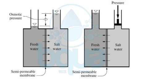
Reverse osmosis (RO) is basially the reverse of the osmosis process. Scientists found that all that is required to reverse the process of osmosis is a suitable semipermeable membrane and applying a pressure to the concentrated salt solution above the applied and osmotic back-pressures, thereby forcing pure water through the semipermeable membrane. In other words, reverse osmosis is the process where water containing inorganic salts (minerals), suspended solids, soluble and insoluble organics, aquatic microorganisms, and dissolved gases (collectively called source water constituents or contaminants) is forced under pressure through a semipermeable membrane. Semipermeable refers to a membrane that selectively allows water to pass through it at much higher rate than the transfer rate of any constituents contained in the water. Learn more about pressure driven membranes here. If water of high salinity is separated from water of low salinity via a semipermeable membrane, a natural process of transfer of water will occur from the low-salinity side to the high-salinity side of the membrane until the salinity on both sides reaches the same concentration. This natural process of water transfer through a membrane driven by the salinity gradient occurs in every living cell; it is known as osmosis.
The hydraulic pressure applied on the membrane by the water during its transfer from the low-salinity side of the membrane to the high-salinity side is termed osmotic pressure. Osmotic pressure is a natural force similar to gravity and is proportional to the difference in concentration of total dissolved solids (TDS) on both sides of the membrane, the source water temperature, and the types of ions that form the TDS content of the source water. This pressure is independent of the type of membrane itself. In order to remove fresh (low-salinity) water from a high-salinity source water using membrane separation, the natural osmosis-driven movement of water must be reversed, i.e., the freshwater has to be transferred from the high-salinity side of the membrane to the low-salinity side. For this reversal of the natural direction of freshwater flow to occur, the high-salinity source water must be pressurized at a level higher than the naturally occurring osmotic pressure.
If the high-salinity source water is continuously pressurized at a level higher than the osmotic pressure and the pressure losses for water transfer through the membrane, a steady-state flow of freshwater from the high-salinity side of the membrane to the low-salinity side will occur, resulting in a process of salt rejection and accumulation on one side of the membrane and freshwater production on the other. This process of forced movement of water through a membrane in the opposite direction to the osmotic force driven by the salinity gradient is known as reverse osmosis (RO).
The rate of water transport through the membrane is several orders of magnitude higher than the rate of passage of salts. This significant difference between water and salt passage rates allows membrane systems to produce freshwater of very low mineral content. The applied feed water pressure counters the osmotic pressure and overcomes the pressure losses that occur when the water travels through the membrane, thereby keeping the freshwater on the low-salinity (permeate) side of the membrane until this water exits the membrane vessel.

Osmosis and Reverse Osmosis Process
The salts contained on the source water (influent) side of the membrane are retained and concentrated; they are ultimately evacuated from the membrane vessel for disposal. As a result, the RO process results in two streams—one of freshwater of low salinity (permeate) and one of feed source water of elevated salinity (concentrate, brine or retentate), as shown in the figure above. While semipermeable RO membranes reject all suspended solids, they are not an absolute barrier to dissolved solids (minerals and organics alike). Some passage of dissolved solids will accompany the passage of freshwater through the membrane. The rates of water and salt passage are the two key performance characteristics of Reverse Osmosis membranes.

Reverse Osmosis Process Drawing
