


What are the USA Drinking Water Standards
Drinking water standards have been set by a number of countries and international organizations. The number of standards published by these organizations and the frequency of their revision is increasing. Hence, only references for the current standards will be provided so that the most recent version can be obtained from the appropriate agency.
Summary Listing of USA Drinking Water Standards
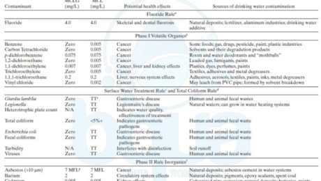
Current and proposed drinking water standards are summarized in Tables 1.9 to 1.11.The background and current status of anticipated USEPA drinking water regulations are reviewed annually in the Journal of the American Water Works Association (Pontius, 1990a, 1992, 1993a, 1995, 1996a, 1997b, 1998; Pontius and Roberson, 1994).

USEPA Drinking Water Standards USA Table

USEPA Drinking Water Standards USA Table continued

USEPA Drinking Water Standards USA Table continued 2

USEPA Drinking Water Standards USA Table Continued 3

USEPA Drinking Water Standards USA Table Continued 4
Drinking water standards in Canada
In Canada, provision of drinking water is primarily the responsibility of the provinces and municipalities. The federal Department of Health conducts research, provides advice, and in collaboration with the health and environment ministries of the provinces and territories, established guidelines for drinking water standards quality under the auspices of the Federal-Provincial Subcommittee of Drinking Water.A publication entitled Guidelines for Canadian Drinking Water Quality (Health and Welfare Canada, 1996) identifies substances that have been found in drinking water and are known or suspected to be harmful. For each substance, the Guidelines establish the maximum acceptable concentration (MAC) that can be permitted in water used for drinking. The MAC is similar to the USEPA MCL.
Drinking water standards in Mexico
In Mexico, the federal Secretariat of Health has the authority for setting drinking water standards. A national law analogous to the U.S. SDWA does not exist, but Mexico has set standards for a number of microbiological and chemical contaminants that they refer to as norms (Secretariat of Health, 1993). Compliance with the DRINKING WATER STANDARDS, REGULATIONS, AND GOALS 1.39 norms established by the federal government is mandatory.The norms are similar to the USEPA MCLs in that they are set at the federal level, and then the water purveyors are required to conduct monitoring in accordance with the norms and to meet the values set. The standards include sampling and analytical requirements as well as reporting requirements. Implementation is carried out by the Secretariat of Health, other government entities, and the National Water Commission.
Drinking water standards by the World Health Organization (WHO)
The World Health Organization (WHO) is a specialized agency of the United Nations with primary responsibility for international health matters and public health. In carrying out that responsibility, it assembles from time to time international experts in the field of drinking water to establish Guidelines for Drinking water Quality (WHO, 1996).The primary aim of this publication is the protection of public health. These Guidelines are published primarily as a basis for the development of national drinking water standards, which, if properly implemented, will ensure the safety of drinking water supplies by eliminating known hazards. These Guidelines values are not mandatory limits. Each country must consider the Guidelines values in the context of local or national environmental, social, economic, and cultural conditions. They can then select which of the Guidelines are applicable to their situation and may choose to make adjustments to suit local conditions. The issues of monitoring, reporting, and enforcement are solely left to the discretion of the governmental entity using the WHO Guidelines. USEPA is an active participant in the development of the Guidelines, and the procedures used are in some ways similar to those used to develop the U.S. drinking water regulations.
Drinking water standards by the European Union (EU)
The European Union (EU) is a voluntary economic alliance of member states. Through the European Commission, directives are created that must then be adopted and implemented by member states. Therefore, EU members must have enforceable drinking water standards that cannot be less stringent than the limit values set out in the directive. Of course, member states can set more stringent standards if they wish. In July 1980, the Commission adopted directive 80/778/EEC relating to the quality of water intended for human consumption (EEC, 1980). On January 4, 1995, the European Commission adopted a proposal to simplify, consolidate, and update the directive. The proposal reduces the number of parameters from 66 to 48 (including 13 new contaminants), obliges member states to fix values for additional health parameters as needed, adds more flexibility to redress failures, allows efficient monitoring by including a number of indicator parameters, and finally, adds a requirement for annual reports to the consumer (EC, 1996).This proposal was adopted by the Council of the European Union on December 19, 1997 (EU, 1997).
Contact us for more information regarding this article or water treatment options for your water.
Qué es el sólidos suspendidos totales – Definición
La concentración total de sólidos suspendidos es una medida del peso total de los residuos sólidos contenidos en el agua de la fuente; y se presenta habitualmente en miligramos por litro o partes por millón. Los sólidos suspendidos totales también se pueden definir como un análisis de laboratorio que mide el peso de los sólidos suspendidos en un volumen especÃfico. Se utiliza para medir con precisión (dentro de las limitaciones de la prueba) la concentración de sólidos suspendidos. La medición de sólidos suspendidos totales es el método estándar para medir el peso de sólidos suspendidos. El método utiliza un filtro de membrana de 0,45 micrones.
Procedimiento de prueba de medición de sólidos suspendidos totales
El total de sólidos suspendidos es la prueba estándar más precisa para controlar la cantidad de material suspendido en una muestra. Los problemas con esto son:
1. No nos dice nada sobre el número de partÃculas.
2. No nos dice nada sobre el tamaño de las partÃculas.
3. Es solo una medida cruda del potencial de ensuciamiento de las partÃculas.
4. No mide ninguna partÃcula de menos de 0.45 micras de diámetro.
Sin embargo, incluso con sus limitaciones, puede ser una herramienta valiosa para monitorear la carga de sólidos en un sistema de ósmosis inversa.
El sólidos suspendidos totales se mide filtrando un volumen conocido de agua (tÃpicamente 1 L) a través de un filtro de fibra de vidrio previamente pesado, secando el filtro con los sólidos retenidos entre 103 y 105 C, y luego pesando el filtro nuevamente después del secado. La diferencia entre el peso del filtro seco y del filtro limpio, dividida por el volumen de la muestra filtrada, refleja la cantidad total de sólidos particulados (suspendidos) en el agua de la fuente.
Cabe señalar que debido a que el agua salina contiene sólidos disueltos que se cristalizarán y se convertirán en partÃculas sólidas cuando la muestra se caliente a 103 a 105 C. A menudo, el análisis de sólidos en suspensión total de agua salina completado de acuerdo con los métodos estándar para el análisis de agua y aguas residuales produce un contenido de sólidos en suspensión total erróneamente alto en el agua. Cuanto mayor sea la salinidad del agua de la fuente y cuanto menor sea el contenido de partÃculas, más inexacta será esta medición. Con el fin de abordar el desafÃo asociado con el método estándar de medición con sólidos suspendidos totales, se recomienda lavar los sólidos retenidos en el filtro rociando el filtro con agua desionizada antes de secar. A menos que la muestra de sólidos de agua de origen se lave antes de secar, los resultados de esta muestra carecen de significado.
Si la prueba de sólidos suspendidos totales del laboratorio se completa correctamente y la muestra filtrada se lava bien, este parámetro generalmente proporciona una medida mucho más precisa del contenido real de sólidos particulados en el agua de origen que la turbidez, ya que explica el peso real del material particulado presente en la muestra. A modo de comparación, la medición de la turbidez depende del tamaño, la forma y el color de las partÃculas, y generalmente no refleja partÃculas de tamaño muy pequeño (es decir, partÃculas de 0.5 µm o menos), como limo fino y picoalgae. De hecho, un cambio en la relación del sólidos suspendidos totales a la turbidez es un buen indicador de un cambio en el tamaño de las partÃculas contenidas en el agua de origen, que puede ser provocada por la proliferación de algas, tormentas, vientos fuertes y otros eventos similares. lo que puede resultar en la resuspensión de sólidos de los sedimentos del fondo a la columna de agua.
TÃpicamente, un aumento en la proporción de sólidos suspendidos totales / turbidez es indicativo de un desplazamiento de los sólidos particulados hacia partÃculas de tamaño más pequeño. Por ejemplo, en condiciones de ausencia de floración de algas, la relación sólidos suspendidos totales / turbidez de una muestra procesada de manera adecuada suele estar en el rango de 1.5 a 2.5, es decir, el agua con una turbidez de 2 NTU tendrÃa una concentración de sólidos suspendidos totales de 3 a 5 mg / l. Durante las floraciones de algas pesadas dominadas por algas de tamaño pequeño (pico y micro), el sólidos suspendidos totales del agua de origen podrÃa aumentar más de 10 veces (por ejemplo, a 40 mg / L), mientras que la turbidez del agua de origen podrÃa multiplicarse por 2 a Solo 3 veces: para este ejemplo, estarÃa en un rango de 4 a 6 NTU, con un aumento correspondiente en la relación sólidos suspendidos totales / NTU de 2/1 a entre 6/1 y 10/1.
Clean In Place – Membrane Cleaning CIP System
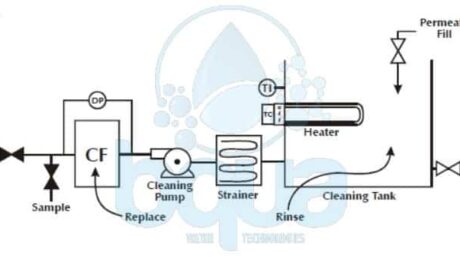
A Clean in place CIP system is a very effective method widely used by RO Systems manufacturers and operators to preserve and also clean fouled or scaled reverse osmosis system RO membranes. Using certain chemicals and following procedures guided by each RO Membrane manufacturers. With few exceptions, all reverse osmosis systems and other membrane systems are subject to fouling by one or more source water components and therefore require periodic cleaning. Clean In Place CIP Membrane cleaning is usually performed without removing membranes from the pressure vessels or the system. A Clean In Place CIP system is designed to prepare and recirculate chemical solutions through some of or all membrane modules at low pressure.
The CIP system can also be used to feed special membrane post treatment chemicals. Not to be confused with membrane system post treatment. Membrane performance require post-treatment equipment in some cases. The clean in place CIP system also serves to prepare and transfer membrane storage solutions, or preservatives. Membrane “pickling” solutions prevent microbial growth and in some cases prevent freezing when the membrane system is shut down for extended periods, typically more than a week. The clean in place system for a Reverse Osmosis System or Nano-Filtration system should be designed to accommodate all cleaning and membrane storage solutions expected to be used at the plant.
Inadequate clean in place CIP System procedures will result in ineffective cleaning results. We will discuss the major parameters of membrane cleaning followed by cleaning instructions from RO membrane manufacturers and step-by-step procedure. The major parameters are:
- Chemicals
- Temperature
- Flow rate
- Time
Clean In Place Chemicals
We won’t remove a carbonate scale with caustic or remove a biofilm with low pH. We must use the right chemical(s) to dissolve as much of the foulant / scalant as possible. Things that dissolve will leave the Reverse Osmosis System easily. It is the things that don’t dissolve which give us the problems. Please contact BQUA for more information about choosing the right chemical for your cleaning.
Clean In Place Temperature
Temperature affects chemical reactions. In general, the rate of most chemical reactions will double with every 10°C increase in temperature. In other words, we can get the job done quicker if the cleaning solution is warmer. If the cleaning solution temperature is less than 16°C (60°F), then cleaning will have no effect since the water is too cold. The cleaning solution temperature should be at least 21°C (70°F). Even better, get the temperature above 27°C (80°F).
Clean In Place Flow Rate
Flow rate is critical for removing fouling particles. It is unlikely that we will be able to dissolve particles completely. We, therefore, must physically remove them. We do this with turbulence. The higher the flow rate, the higher the turbulence. The higher the turbulence, the more particles removed.
Clean In Place Time
Frequently RO membrane manufacturers and chemical cleaning vendors recommend a one-hour cleaning. If the scalant/foulant is stubborn, some soaking time prior to, or after, we recommend circulating the solution. This is fine for lightly fouled/scaled elements. This may work if cleaning is initiated when the Normalized Permeate Flow NPF has dropped no more than 10-15%Â and/or the Differential Pressure DP across a stage has increased no more than 15-25%. And will not work if fouling/scaling has been allowed to progress. It is not unusual to have to clean severely fouled RO Membrane elements for 72 continuous hours. Use clean in place CIP monitoring sheets during a cleaning, and trending graphs following a cleaning, to determine when cleaning completes. Much more time than usually recommended may be required.

BQUA Clean In Place CIP System design
Clean In Place CIP System Procedure
RO membrane manufacturers provide the following clean in place CIP System procedures. This is followed by an illustrated, procedure which contains the most important points of a good clean in place membrane cleaning.
RO Membrane Element Cleaning and Flushing
The RO membrane elements in place in the pressure tubes are cleaned by recirculating the cleaning solution across the high-pressure side of the membrane at low pressure and relatively high flow. That’s when we use a CIP system. A general procedure for cleaning the Reverse Osmosis membrane elements is as follows:
- Flush the pressure tubes by pumping clean, chlorine-free product water from the cleaning tank (or equivalent source) through the pressure tubes to drain for several minutes.
- Mix a fresh batch of the selected cleaning solution in the cleaning tank, using clean product water. Circulate the cleaning solution through the pressure tubes for approximately one hour or the desired period of time. At a flow rate of 35 to 40 gpm (133 to 151 L/min.) per pressure tube for 8.0(20.3 cm) and 8.5(21.6 cm) inch pressure tubes, 15 to 20 gpm (57 to 76 L/min.) for 6.0(15.2 cm) pressure tubes, or 9 to 10 gpm (34 to 38 L/min.) for 4.0 inch pressure tubes.
- After completion of cleaning, drain and flush the cleaning tank; then fill the cleaning tank with clean product water for rinsing.
- Rinse the pressure tubes by pumping clean, chlorine-free product water from the cleaning tank (or equivalent source) through the pressure tubes to drain for several minutes.
- After rinsing the Reverse Osmosis system, operate it with the product dump. Open valves until the product water flows clean and is free of any foam or residues of cleaning agents (usually 15 – 30 minutes).
If the system shuts down for more than 24 hours, the best procedure for storage is soaking the element in an aqueous solution. With 20 percent, by weight, glycerine or propylene glycol and 1.0 percent, by weight, sodium bisulfite or SMBS Sodium Metabisulfite.

Example on Before and After CIP Chemical Membrane Cleaning in a Brackish Reverse Osmosis System
CIP System in Multi-Array Systems
For multi-array (tapered) systems the flushing and soaking operations can happen simultaneously in all arrays. You should carry out separately high flow re-circulation, however, for each array. So the flow rate is not too low in the first or too high in the last. This can be accomplished either by using one cleaning pump and operating one array at a time, or using a separate cleaning pump for each array.

RO membrane clean in place cip system overall procedure
What is Dissolved Air Flotation Definition – DAF Unit
Dissolved air flotation (DAF) technology is very suitable for removal of floating particulate foulants such as algal cells, oil, grease or other contaminants that cannot be effectively removed by sedimentation or filtration. Dissolved Air Flotation DAF system can typically produce effluent turbidity of <0.5 NTU and can be combined in one structure with dual-media gravity filters for sequential pretreatment of seawater. Dissolved Air Flotation (DAF) process uses very small air bubbles to float light particles and organic substances (oil, grease) contained in the seawater. The floated solids are collected at the top of the DAF tank and skimmed off for disposal, while the low turbidity seawater is collected near the bottom of the tank. The time (and therefore, the size of flocculation tank) needed for the light fine particulates contained in the seawater to form large flocs is usually 2 to 3 times shorter than that in conventional flocculation tanks, because the flocculation process is accelerated by the air bubbles released in the flocculation chamber of the DAF tanks. In addition, the surface loading rate for removal of light particulates and floatable substances by DAF is approximately 10 times lower than that needed for conventional sedimentation. Another benefit of DAF as compared to conventional sedimentation is the higher density of the formed residuals (sludge). While residuals collected at the bottom of sedimentation basins typically have concentration of only 0.3 to 0.5 % solids, DAF residuals (which are skimmed off the surface of the DAF tank) contain solids concentration of 1 to 3 %. In some full-scale applications, the DAF process is combined with granular media filters to provide a compact and robust pretreatment of seawater with high algal and/or oil and grease content. Although this combined DAF/filter configuration is very compact and cost-competitive, it has three key disadvantages:
(1) complicates the design and operation of the pretreatment filters;
(2) DAF system loading is controlled by the filter loading rate and therefore, DAF tanks are typically oversized;
(3) Flocculation tanks must be coupled with individual filter cells. The feasibility of Dissolved Air Flotation DAF unit use for seawater pretreatment is determined by seawater quality and governed by source water turbidity and overall lifecycle pretreatment costs.
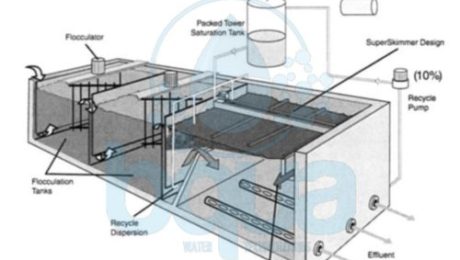
In flotation, the effects of gravity settling are offset by the buoyant forces of small air bubbles. These air bubbles are introduced to the flocculated water, where they attach to floc particles and then float to the surface. Flotation is typically sized at loading rates up to 10 times that for conventional treatment. Higher rates may be possible on high-quality warm water. Dissolved air flotation (DAF) is an effective alternative to sedimentation or other clarification processes. Modern DAF technology was first patented in 1924 by Peterson and Sveen for fiber separation in the pulp and paper industry (Kollajtis, 1991). The process was first used for drinking water treatment in Sweden in 1960 and has been widely used in Scandinavia and the United Kingdom for more than 30 years. Previous uses of the process in the United States have been to thicken waste-activated sludge in biological wastewater treatment, for fiber separation in the pulp and paper industry, and for mineral separation in the mining industry. Only recently has this process gained interest for drinking water treatment in North America. It is especially applicable when treating for algae, color, and low-turbidity water. The first use in the United States was at New Castle, New York, in a 7.5 mgd (28 ML per day) plant that began operation in 1993. A typical DAF unit is shown below:

Typical Dissolved Air Flotation DAF Unit / System
The DAF unit can handle source seawater with turbidity of up to 50 NTU. Therefore, if the source seawater is impacted by high turbidity spikes or heavy solids (usually related to seasonal river discharges or surface runoff), then DAF system may not be a suitable pretreatment option. In most algal bloom events however, seawater turbidity almost never exceeds 30 to 50 NTU, so the DAF technology can handle practically any red tide event. Although a DAF system have much smaller footprint than the conventional flocculation and sedimentation facilities, it includes a number of additional equipment associated with air saturation and diffusion, and with recirculation of portion of the treated flow, and therefore, their construction costs are typically comparable to these of conventional sedimentation basins. Usually, the O&M costs of DAF system is higher than these of gravity sedimentation tanks due to the higher power use for the flocculation chamber mixers, air saturators, recycling pumps, and sludge skimmers. The total power use for a Dissolved Air Flotation – DAF system is usually 2.5 to 3.0 kWh/1 0,000 m3/day of treated source seawater, which is Significantly higher than that for sedimentation systems (0.5 to 0.7 kWh/1 0000 m3/day of treated seawater).
Theory and Operation of a Dissolved Air Flotation DAF Unit
Effective gravity settling of particles requires that they be destabilized, coagulated, and flocculated by using metal salts, polymers, or both. The same is true for DAF. In gravity settling the flocculation process must be designed to create large, heavy floc that settles to the bottom of the basin. In Dissolved Air Flotation DAF unit, flocculation is designed to create a large number of smaller floc particles that can be floated to the surface. For efficient flotation, flocculated particles must be in contact with a large number of air bubbles.
Three mechanisms are at work in this air/floc attachment process:
• Adhesion of air bubbles on the floc surface
• Entrapment of bubbles under the floc
• Absorption of bubbles into the floc structure
The size of air bubbles is important. If bubbles are too large, the resulting rapid rise rate will exceed the laminar flow requirements, causing poor performance. If bubbles are too small, a low rise rate will result and tank size may need to be increased. In a typical Dissolved Air Flotation tank, flocculated water is introduced uniformly across the end of the tank, near the bottom, into the recycle dispersion zone. Recycle is continuously introduced through a distribution system of proprietary nozzles, valves, or orifices. When the recycle flow pressure is suddenly decreased from its operating pressure of 60 to 90 psi (414 to 620 kPa) to atmospheric pressure, saturated air within the recycle stream is released in the form of microbubbles with a size range of 10 to 100/xm, and averaging around 40 to 50/xm. These microbubbles attach to flocculated material by the mechanisms described previously, causing flocculated material to float to the surface. At the surface, the bubble-floc forms a stable and continuously thickening layer of float, or sludge. If left at the surface, the float can thicken to as much as 3% to 6% dry solids. This can be an advantage if solids are to be mechanically dewatered, because solids may be suitable for dewatering without further thickening, or the thickening process can be reduced. Sludge thickness depends on the time it is allowed to remain on the surface and the type of removal system employed.
Dissolved Air Flotation – DAF System – Key Design Criteria
Dissolved Air Flotation DAF system include three key components: flocculation chamber; flotation tank and recycling system. The design criteria for these three components are presented below:
| Flocculation System: | |
| Minimum Number of Tanks | 4 |
| Velocity Gradient | 30 to 120 s^-1 |
| Contact Time | 10 to 20 min |
| Flocculation Chambers in Series | 2 to 4 |
| Water Depth | 3.5 to 4.5 m |
| Type of Mixer | Vertical-shaft with hydrofoil blades |
| Blade Area/Tank Area | 0.1 to 0.2 % |
| Shaft Speed | 40 to 60 rpm |
| Flotation Chamber: | |
| Minimum Number of Tanks | 4 (same as filter cells if combined with filters) |
| Tank Width | 3 to 10 m |
| Tank Length | 8 to 12 m |
| Tank Depth | 2.5 t0 3m |
| Surface Loading Rate | 10 to 40 m3/m3/h |
| Hydraulic Detention Time | 10 to 15 min |
| Treated Water Recycle System: | |
| Recycling rate | 6 to 10 % of intake flow |
| Maximum Air Loading | 10 g/m3 |
| Saturator Loading Rate | 60 to 65 m3/m2/h |
| Operating Pressure | 4.0 to 6.5 bars |
Dissolved Air Flotation DAF process with built-in filtration (DAFF) is used at the 136,000 m3/day Tuas seawater desalination plant in Singapore (Kiang et aI., 2007). This pretreatment technology has been selected for this project to address the source water quality challenges associated with the location of the desalination plant’s open intake in a large industrial port (i.e., oil spills) and the frequent occurrence of red tides in the area of the intake. The source seawater has total suspended solids concentration that can reach up to 60 mg/L at times and oil and grease levels in the seawater could be up to 10 mg/L. The facility uses 20 build-in filter DAF unit, two of which are operated as standby. Plastic covers shield the surface of the tanks to prevent impact of rain and wind on DAF operation as well as to control algal growth. Each Dissolved Air Flotation DAF unit is equipped with two mechanical flocculation tanks located within the same DAF vessel. Up to 12 % of the filtered water is saturated with air and recirculated to the feed of the DAF unit.

BQUA Dissolved Air Flotation System – DAF unit
A combination of DAF followed by two-stage dual-media pressure filtration has been successfully used at the 45,400 m3/day El Coloso seawater reverse osmosis SWRO plant is Chile, which at present is the largest desalination plant in South America. The plant is located in the City of Antogofasta, where seawater is exposed to year-round red-tide events, which have the capacity to create frequent particulate fouling and biofouling of the SWRO membranes (Petry et aI., 2007). The DAF system at this plant is combined in one facility with a coagulation and flocculation chamber. The average and maximum flow rising velocities of the DAF system are 22 and 33 m3/m 2/h, respectively. This Dissolved Air Flotation DAF system can be bypassed during normal operations and is typically used during red-tide events . The downstream pressure filters are designed for surface loading rate of 25 m3/m’/h. Ferric chloride at a dosage of 10 mg/L is added ahead of the DAF system for source water coagulation. The DAF system reduces source seawater turbidity to between 0.5 and 1.5 NTU and removes approximately 30 to 40 % of the source seawater organics.
BQUA is a proud manufacturer of Dissovled Air Flotation Systems – DAF Units. Please feel free to contact us anytime with your inquiry and our team of specialists will be ready and glad to help you.
