What is Multi Stage Flash Distillation MSF
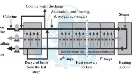
The Multi Stage Flash distillation MSF evaporator vessels is also referred to as flash stages or effects. What happens is that the high-salinity source water is heated to a temperature of 90 to 115°C (194 to 239°F) in a vessel (the heating section in the figure below) to create water vapor. The pressure in the first stage is maintained slightly below the saturation vapor pressure of the water. So when the high-pressure vapor created in the heating section enters into the first stage, its pressure is reduced to a level at which the vapor “flashes†into steam. Steam (waste heat) for the heating section is provided by the power plant co-located with the desalination plant. Each flash stage (effect) has a condenser to turn the steam into distillate. The condensers are equipped with heat exchange tubes, which are cooled by the source water that is fed to the condensers.
schematic multi stage flash distillation process
Entrainment separators (mist eliminators or demister pads) remove the high-salinity mist from the low-salinity rising steam. This steam condenses into pure water (distillate) on the heat exchange tubes and is collected in distillate trays. This is from where it is conveyed to a product water tank. Distillate flows from stage to stage and is collected at the last stage. The concentrate (brine) is generated in each stage and after collection at the last stage some of it typically is recycled to the source water stream in order to reduce the total volume of source water that must be collected by the intake for desalination. The recirculated brine flowing through the interior of the condenser tubes also removes the latent heat of condensation.
As a result, the recirculated brine is also preheated close to maximum operating temperature. Thereby recovering the energy of the condensing vapor and reducing the overall heating needs of the source water. This “brine recycle†feature has been adopted in practically all of the most recent MSF facility designs and allows significant improvement of the overall cost competitiveness of MSF installations. Each flash stage typically produces approximately 1 percent of the total volume of the desalination plant’s condensate. Since a typical MSF unit has 19 to 28 effects, the total MSF plant recovery (i.e., the volume of distillate expressed as a percentage of the total volume of processed source water) is typically 19 to 28 percent. For comparison, Reverse Osmosis seawater desalination SWRO plants have a recovery of 40% to 45%. The latest Multi Stage Flash Distillation technology has 45-stage units—i.e., can operate at 45% recovery. This feature allows it to compete with Reverse Osmosis systems in terms of recovery.
Historically, MSF was the first commercially available thermal desalination technology. It was applied to produce potable water on a large-scale, which explains its popularity. MSF plants represent over 80% of thermally desalinated water today. The gained output ratio GOR for MSF systems is typically between 2 and 8; the latest MSF technology has a GOR of 7 to 9. The pumping power required for the operation of the MSF systems is 2.0 to 3.5 kWh/m3 (7.6 to 13.3 kWh/1000 gal) of product water.
Reference: “Desalination Engineering” by Nikolay Voutchkov
- Published in Technology, Water Treatment
What is Multi Effect Distillation MED
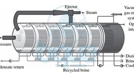
In Multi Effect Distillation MED systems, saline source water is typically not heated; cold source water is sprayed via nozzles or perforated plates over bundles of heat exchange tubes. This feed water sprayed on the tube bundles boils, and the generated vapor passes through mist eliminators. Which collect brine droplets from the vapor. The feed water that turned into vapor in the first stage (effect) is introduced into the heat exchange tubes of the next effect. Because the next effect is maintained at slightly lower pressure, although the vapor is slightly cooler, it still condenses into freshwater at this lower temperature.
This process of reducing the ambient pressure in each successive stage allows the feed water to undergo multiple successive boilings without the introduction of new heat. Steam flowing through the exchange tubes is condensed into pure water and collected from each effect. Heating steam (or vapor) introduced in the heat exchange tubes of the first effect is provided from an outside source by a steam ejector. The Multi Effect Distillation MED system shown in the figure below is also equipped with a brine recycle system. It allows the introduction of warmer-than-ambient water in the first effects of the system. Thereby reducing both the volume of feed water that must be collected by the plant intake system and the overall energy needs of the system.
The main difference between the Multi Effect Distillation MED and Multi Stage Flash Distillation MSF processes is that while vapor is created in an MSF system through flashing, evaporation of feed water in MED is achieved through heat transfer from the steam in the condenser tubes into the source water sprayed onto these tubes.
schematic multiple effect distillation process system
This heat transfer at the same time results in condensation of the vapor to freshwater. Multi Effect Distillation MED desalination systems typically operate at lower temperatures than MSF plants. Maximum brine concentrate temperature of 62 to 75°C versus 115°C) and yield higher GORs.
The newest Multi Effect Distillation MED technologies include vertically positioned effects (vertical tube evaporators). This may yield a GOR of up to 24 kg of potable water per kilogram of steam. Pumping power required for operation of Multi Effect Distillation MED systems is lower than that typically needed for MSF plants. It is equal to 0.8 to 1.4 kWh/m3/3.0 to 5.3 kWh/1000 gallons of product water. Therefore, Multi Effect Distillation MED is now increasingly gaining ground over MSF desalination. Especially in the Middle East, where thermal desalination is still the predominant method for producing potable water from seawater.
Reference: “Desalination Engineering” by Nikolay Voutchkov
- Published in Technology, Water Treatment
What is Vapor Compression VC
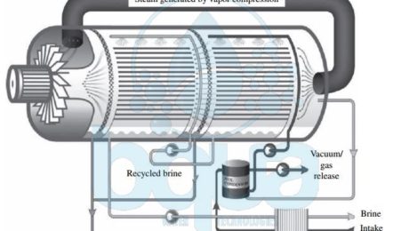
Vapor Compression VC is one type of thermal desalination technologies which also include Muti Stage Flash Distillation MSF and Multi Effect Distillation MED. In Vapor Compression VC, the heat source for vapor compression (VC) systems is compressed vapor produced by a mechanical compressor or a steam jet ejector rather than a direct exchange of heat from steam . In Vapor Compression VC systems the source water is evaporated and the vapor is conveyed to a compressor. The vapor is then compressed to increase its temperature to a point adequate to evaporate the source water sprayed over tube bundles through which the vapor is conveyed. As the compressed vapor exchanges its heat with the new source water being sprayed on the evaporation tubes, it is condensed into pure water. A feed water preheater (plate-type heat exchange) is used to start the process and reach evaporation temperature. Vapor Compression VC and Multi Effect Distillation MED work based on similar principles.
vapor compression tehnology thermal desalination process system
However, in Multi Effect Distillation MED steam produced by source water evaporation is introduced and condensed in a separate condenser. Condenser is located in the downstream effect. In Vapor Compression VC, the steam generated from evaporation of new source water sprayed on the outside surface of the heat exchange tubes is recirculated by the vapor compressor. It is then introduced into the inner side of the of the same heat exchange tubes in which it condenses to form distillate. Vapor Compression VC desalination has found applications mostly in small municipal and resort water supply systems. As well as industrial applications. The total amount of power required for the operation of mechanical Vapor Compression VC systems is typically 8 to 12 kWh/m3 (30 to 45 kWh/1000 gal) of product water.
Reference: “Desalination Engineering” by Nikolay Voutchkov
- Published in Technology, Water Treatment


